Information injection-pump assembly
BOSCH
9 400 617 035
9400617035
ZEXEL
106671-9030
1066719030
Rating:
Service parts 106671-9030 INJECTION-PUMP ASSEMBLY:
1.
_

7.
COUPLING PLATE
8.
_
9.
_
10.
NOZZLE AND HOLDER ASSY
11.
Nozzle and Holder
12.
Open Pre:MPa(Kqf/cm2)
13.
NOZZLE-HOLDER
14.
NOZZLE
15.
NOZZLE SET
Include in #1:
106671-9030
as INJECTION-PUMP ASSEMBLY
Cross reference number
BOSCH
9 400 617 035
9400617035
ZEXEL
106671-9030
1066719030
Zexel num
Bosch num
Firm num
Name
106671-9030
9 400 617 035
DAEWOO
INJECTION-PUMP ASSEMBLY
D2366TI K
D2366TI K
Calibration Data:
Adjustment conditions
Test oil
1404 Test oil ISO4113 or {SAEJ967d}
1404 Test oil ISO4113 or {SAEJ967d}
Test oil temperature
degC
40
40
45
Nozzle and nozzle holder
105780-8140
Bosch type code
EF8511/9A
Nozzle
105780-0000
Bosch type code
DN12SD12T
Nozzle holder
105780-2080
Bosch type code
EF8511/9
Opening pressure
MPa
17.2
Opening pressure
kgf/cm2
175
Injection pipe
Outer diameter - inner diameter - length (mm) mm 8-3-600
Outer diameter - inner diameter - length (mm) mm 8-3-600
Overflow valve
131424-4420
Overflow valve opening pressure
kPa
157
123
191
Overflow valve opening pressure
kgf/cm2
1.6
1.25
1.95
Tester oil delivery pressure
kPa
157
157
157
Tester oil delivery pressure
kgf/cm2
1.6
1.6
1.6
Direction of rotation (viewed from drive side)
Right R
Right R
Injection timing adjustment
Direction of rotation (viewed from drive side)
Right R
Right R
Injection order
1-5-3-6-
2-4
Pre-stroke
mm
4.4
4.35
4.45
Beginning of injection position
Drive side NO.1
Drive side NO.1
Difference between angles 1
Cal 1-5 deg. 60 59.5 60.5
Cal 1-5 deg. 60 59.5 60.5
Difference between angles 2
Cal 1-3 deg. 120 119.5 120.5
Cal 1-3 deg. 120 119.5 120.5
Difference between angles 3
Cal 1-6 deg. 180 179.5 180.5
Cal 1-6 deg. 180 179.5 180.5
Difference between angles 4
Cyl.1-2 deg. 240 239.5 240.5
Cyl.1-2 deg. 240 239.5 240.5
Difference between angles 5
Cal 1-4 deg. 300 299.5 300.5
Cal 1-4 deg. 300 299.5 300.5
Injection quantity adjustment
Adjusting point
A
Rack position
10.1
Pump speed
r/min
1100
1100
1100
Average injection quantity
mm3/st.
166.5
164.5
168.5
Max. variation between cylinders
%
0
-2
2
Basic
*
Fixing the lever
*
Boost pressure
kPa
66.7
66.7
Boost pressure
mmHg
500
500
Injection quantity adjustment_02
Adjusting point
B
Rack position
4.1+-0.5
Pump speed
r/min
250
250
250
Average injection quantity
mm3/st.
13
11.5
14.5
Max. variation between cylinders
%
0
-15
15
Fixing the rack
*
Boost pressure
kPa
0
0
0
Boost pressure
mmHg
0
0
0
Injection quantity adjustment_03
Adjusting point
C
Rack position
-
Pump speed
r/min
100
100
100
Average injection quantity
mm3/st.
92
92
Fixing the lever
*
Boost pressure
kPa
0
0
0
Boost pressure
mmHg
0
0
0
Boost compensator adjustment
Pump speed
r/min
500
500
500
Rack position
7.15
Boost pressure
kPa
16.7
14.7
18.7
Boost pressure
mmHg
125
110
140
Boost compensator adjustment_02
Pump speed
r/min
500
500
500
Rack position
9.15
Boost pressure
kPa
53.3
53.3
53.3
Boost pressure
mmHg
400
400
400
Timer adjustment
Pump speed
r/min
750--
Advance angle
deg.
0
0
0
Remarks
Start
Start
Timer adjustment_02
Pump speed
r/min
700
Advance angle
deg.
0.5
Timer adjustment_03
Pump speed
r/min
1100
Advance angle
deg.
3
2.5
3.5
Remarks
Finish
Finish
Test data Ex:
Governor adjustment
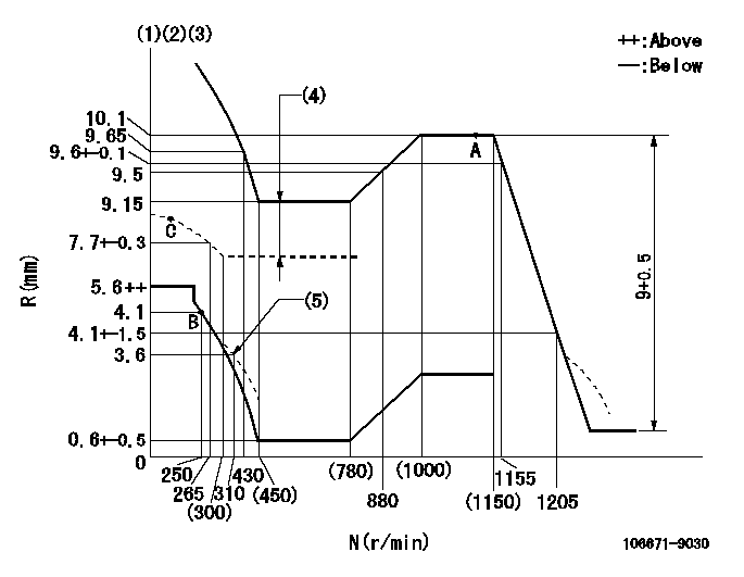
N:Pump speed
R:Rack position (mm)
(1)Tolerance for racks not indicated: +-0.05mm.
(2)Deliver with rack limit not operating
(3)Microswitch adjustment unnecessary.
(4)Boost compensator stroke: BCL
(5)Damper spring setting
----------
BCL=2+-0.1mm
----------
----------
BCL=2+-0.1mm
----------
Speed control lever angle

F:Full speed
----------
----------
a=(9deg)+-5deg
----------
----------
a=(9deg)+-5deg
0000000901
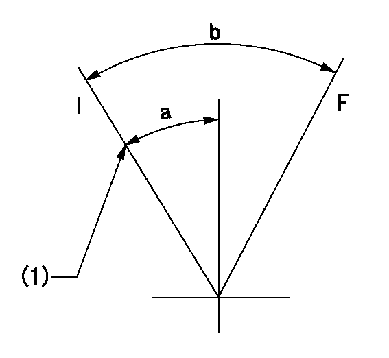
F:Full load
I:Idle
(1)Stopper bolt setting
----------
----------
a=18.5deg+-5deg b=31deg+-3deg
----------
----------
a=18.5deg+-5deg b=31deg+-3deg
Stop lever angle

N:Pump normal
S:Stop the pump.
(1)Use the hole at R = aa
----------
aa=45mm
----------
a=71deg+-5deg b=39deg+-5deg
----------
aa=45mm
----------
a=71deg+-5deg b=39deg+-5deg
Timing setting

(1)Pump vertical direction
(2)Coupling's key groove position for the No. 6 cylinder's beginning of injection
(3)-
(4)-
----------
----------
a=(70deg)
----------
----------
a=(70deg)
Information:
Observe the safe working load limits of all lifting and blocking devices and keep a safe distance from suspended/blocked loads. Personnel may be seriously injured or killed by falling loads.
Problem
There have been isolated instances where the Diesel Exhaust Fluid (DEF) pressure sensor within the DEF pump breaks and DEF leaks into the DEF pump. DEF wicks up the wiring between the DEF pump and the interface connector. The DEF then shorts across the pins of the connector leading to the issue.Solution
Do not operate or work on this product unless you have read and understood the instruction and warnings in the relevant Operation and Maintenance Manuals and relevant service literature. Failure to follow the instructions or heed the warnings could result in injury or death. Proper care is your responsibility.
Using an electronic service tool, generate a Product Status Report (PSR) with the engine running histograms and abnormal shutdown history included.
Check to see if the DEF system has been contaminated. Examples of contaminants are fuels, oils, coolant, and wind shield washer fluid.
DEF Injector
Remove electrical connector and examine it for the presence of DEF.
Illustration 1 g06386447
Typical example of a DEF injector
(1) Location of the serial number
(2) DEF injector
(3) DEF injector electrical connectorNote: Do not remove DEF injector from Clean Emissions Module (CEM).
Illustration 2 g06386460
Typical example DEF injector electrical connector
Examine the OEM harness connection for the presence of DEF in the connector.
31-Pin Connector
Illustration 3 g06386503
Typical example of a 31-pin connector
Confirm that the 31-pin connector is securely tightened.
Illustration 4 g06386512
Typical example of a 31-pin connector with blanking caps
(4) Blanking caps
Ensure that blanking caps (4) are in place on the unused pins on both sides 31-pin connector.
Illustration 5 g06388958
Typical example of a 31-pin connector O-Ring location
Disconnect 31-pin connector and ensure that the O-Ring is in the correct position in the machine side of the connection. Position (Y) shows where the red O-Ring seal is located.
Check for fluid contamination in the 31-pin connector. If contaminant is present, determine what the contaminant is. Check for DEF, which leaves white residue marks or the PH level (9 to 9.5).Check for diesel using HC strips. Check for water (PH 7).
Check for signs of overheating or corrosion.
Machine Fuse
Inspect DEF fuse condition and the fuse rating.
DEF Injector
Using a suitable multimeter, measure the electrical resistance on DEF injector connector pin 1 to pin 2. If the measured resistance is less than 6 Ohms or more than 8 Ohms, a fault in the injector is detected.
Check for signs of the presence of DEF within the machine electrical wires connected to the DEF injector.
Check the history of the machine for previous DEF injector issues.
Use the electronic service tool to generate a PSR and obtain an abnormal shutdown, engine running histograms, and application history.
Check for logged 3361-5 or 3821-5 "Aftertreatment #1 DEF Dosing Unit: Current Below Normal" diagnostic codes.
Using a suitable multimeter, measure the resistance between the following points:
31-pin connector pin 11 and pin 2 DEF injector connector.
31-pin connector pin 12 and pin 1 DEF injector connector.
If the measured resistance is greater than 2 Ohms. There is an open
Have questions with 106671-9030?
Group cross 106671-9030 ZEXEL
Mitsubishi-Heav
Komatsu
Daewoo
106671-9030
9 400 617 035
INJECTION-PUMP ASSEMBLY
D2366TI
D2366TI