Information injection-pump assembly
ZEXEL
106671-9020
1066719020
KOMATSU
6152711410
6152711410

Rating:
Cross reference number
ZEXEL
106671-9020
1066719020
KOMATSU
6152711410
6152711410
Zexel num
Bosch num
Firm num
Name
Calibration Data:
Adjustment conditions
Test oil
1404 Test oil ISO4113 or {SAEJ967d}
1404 Test oil ISO4113 or {SAEJ967d}
Test oil temperature
degC
40
40
45
Nozzle and nozzle holder
105780-8140
Bosch type code
EF8511/9A
Nozzle
105780-0000
Bosch type code
DN12SD12T
Nozzle holder
105780-2080
Bosch type code
EF8511/9
Opening pressure
MPa
17.2
Opening pressure
kgf/cm2
175
Injection pipe
Outer diameter - inner diameter - length (mm) mm 8-3-600
Outer diameter - inner diameter - length (mm) mm 8-3-600
Overflow valve opening pressure
kPa
157
123
191
Overflow valve opening pressure
kgf/cm2
1.6
1.25
1.95
Tester oil delivery pressure
kPa
157
157
157
Tester oil delivery pressure
kgf/cm2
1.6
1.6
1.6
Direction of rotation (viewed from drive side)
Left L
Left L
Injection timing adjustment
Direction of rotation (viewed from drive side)
Left L
Left L
Injection order
1-5-3-6-
2-4
Pre-stroke
mm
3.8
3.75
3.85
Beginning of injection position
Drive side NO.1
Drive side NO.1
Difference between angles 1
Cal 1-5 deg. 60 59.5 60.5
Cal 1-5 deg. 60 59.5 60.5
Difference between angles 2
Cal 1-3 deg. 120 119.5 120.5
Cal 1-3 deg. 120 119.5 120.5
Difference between angles 3
Cal 1-6 deg. 180 179.5 180.5
Cal 1-6 deg. 180 179.5 180.5
Difference between angles 4
Cyl.1-2 deg. 240 239.5 240.5
Cyl.1-2 deg. 240 239.5 240.5
Difference between angles 5
Cal 1-4 deg. 300 299.5 300.5
Cal 1-4 deg. 300 299.5 300.5
Injection quantity adjustment
Adjusting point
A
Rack position
10.1
Pump speed
r/min
1050
1050
1050
Average injection quantity
mm3/st.
152.5
150.5
154.5
Max. variation between cylinders
%
0
-3
3
Basic
*
Fixing the lever
*
Boost pressure
kPa
86.6
86.6
Boost pressure
mmHg
650
650
Injection quantity adjustment_02
Adjusting point
B
Rack position
5+-0.5
Pump speed
r/min
300
300
300
Average injection quantity
mm3/st.
18
16.5
19.5
Max. variation between cylinders
%
0
-15
15
Fixing the rack
*
Boost pressure
kPa
0
0
0
Boost pressure
mmHg
0
0
0
Boost compensator adjustment
Pump speed
r/min
500
500
500
Rack position
8.3
Boost pressure
kPa
40
37.3
42.7
Boost pressure
mmHg
300
280
320
Boost compensator adjustment_02
Pump speed
r/min
500
500
500
Rack position
11.1
Boost pressure
kPa
73.3
66.6
80
Boost pressure
mmHg
550
500
600
Timer adjustment
Pump speed
r/min
700--
Advance angle
deg.
0
0
0
Remarks
Start
Start
Timer adjustment_02
Pump speed
r/min
650
Advance angle
deg.
0.5
Timer adjustment_03
Pump speed
r/min
850
Advance angle
deg.
1.2
0.7
1.7
Timer adjustment_04
Pump speed
r/min
1050
Advance angle
deg.
3
2.5
3.5
Remarks
Finish
Finish
Test data Ex:
Governor adjustment
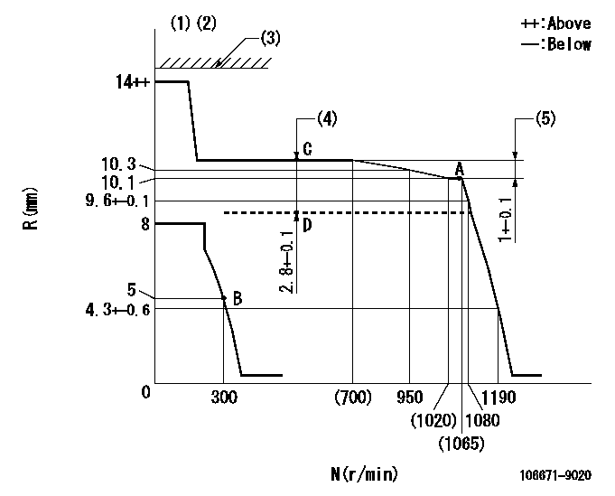
N:Pump speed
R:Rack position (mm)
(1)Notch: K
(2)Tolerance for racks not indicated: +-0.05mm.
(3)Excess fuel lever not set.
(4)Boost compensator stroke
(5)Rack difference between N = N1 and N = N2
----------
K=14 N1=1050r/min N2=500r/min
----------
----------
K=14 N1=1050r/min N2=500r/min
----------
Speed control lever angle
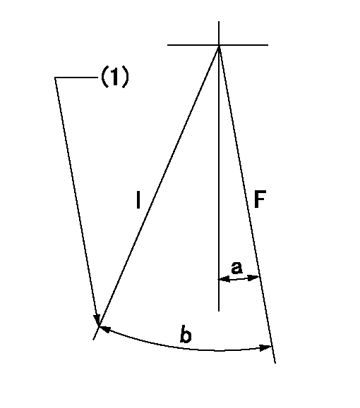
F:Full speed
I:Idle
(1)Stopper bolt setting
----------
----------
a=9deg+-5deg b=27deg+-5deg
----------
----------
a=9deg+-5deg b=27deg+-5deg
Stop lever angle
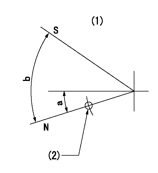
N:Pump normal
S:Stop the pump.
(1)No return spring
(2)Use hole at R = aa (left hand side)
----------
aa=27mm
----------
a=26.5deg+-5deg b=53deg+-5deg
----------
aa=27mm
----------
a=26.5deg+-5deg b=53deg+-5deg
0000001101
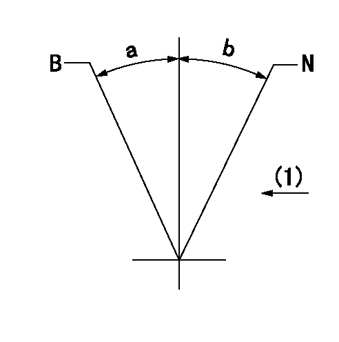
N:Normal
B:When boosted
(1)Drive side
----------
----------
a=(15deg) b=(15deg)
----------
----------
a=(15deg) b=(15deg)
Timing setting

(1)Pump vertical direction
(2)Coupling's key groove position at No 1 cylinder's beginning of injection
(3)-
(4)-
----------
----------
a=(150deg)
----------
----------
a=(150deg)
Information:
Table 1
Repair Kit Part Numbers for Quick Connect DEF Line Fittings
473-2053 5/16"-90 Degree Kit
473-2055 5/16"- Straight Kit
473-2056 3/8"-90 Degree Kit
473-2057 3/8"- Straight Kit Rework Procedure
Table 2
Required Tools
Part Number Part Name
1U-7648 Tube Cutter
Illustration 1 g06433660
Cut the connector end on the corrugated section with the cutter.
Illustration 2 g06433665
Cut the two wires with a tie cutter.
Illustration 3 g06433668
Use a knife or sharp blade to cut the outer sheathing off. Ensure not to cut or damage the inner fluid hose.
Illustration 4 g06433669
Install the hose clamp provided first before installing the connector. Use appropriate size (3/8th or 5/16th) and type (90 degree or straight) fitting.
Illustration 5 g06433672
Fasten the clamp until the two jaws are either in contact or about 2 to 3 mm (0.08 to 0.1 inch) apart.