Information injection-pump assembly
BOSCH
9 400 610 379
9400610379
ZEXEL
106671-8982
1066718982

Rating:
Service parts 106671-8982 INJECTION-PUMP ASSEMBLY:
1.
_
7.
COUPLING PLATE
8.
_
9.
_
11.
Nozzle and Holder
23600-2950A
12.
Open Pre:MPa(Kqf/cm2)
14.7{150}/21.6{220}
14.
NOZZLE
Include in #1:
106671-8982
as INJECTION-PUMP ASSEMBLY
Cross reference number
BOSCH
9 400 610 379
9400610379
ZEXEL
106671-8982
1066718982
Zexel num
Bosch num
Firm num
Name
Calibration Data:
Adjustment conditions
Test oil
1404 Test oil ISO4113 or {SAEJ967d}
1404 Test oil ISO4113 or {SAEJ967d}
Test oil temperature
degC
40
40
45
Nozzle and nozzle holder
105780-8140
Bosch type code
EF8511/9A
Nozzle
105780-0000
Bosch type code
DN12SD12T
Nozzle holder
105780-2080
Bosch type code
EF8511/9
Opening pressure
MPa
17.2
Opening pressure
kgf/cm2
175
Injection pipe
Outer diameter - inner diameter - length (mm) mm 8-3-600
Outer diameter - inner diameter - length (mm) mm 8-3-600
Overflow valve
134424-0920
Overflow valve opening pressure
kPa
162
147
177
Overflow valve opening pressure
kgf/cm2
1.65
1.5
1.8
Tester oil delivery pressure
kPa
157
157
157
Tester oil delivery pressure
kgf/cm2
1.6
1.6
1.6
Direction of rotation (viewed from drive side)
Left L
Left L
Injection timing adjustment
Direction of rotation (viewed from drive side)
Left L
Left L
Injection order
1-4-2-6-
3-5
Pre-stroke
mm
4.6
4.54
4.6
Beginning of injection position
Drive side NO.1
Drive side NO.1
Difference between angles 1
Cal 1-4 deg. 60 59.75 60.25
Cal 1-4 deg. 60 59.75 60.25
Difference between angles 2
Cyl.1-2 deg. 120 119.75 120.25
Cyl.1-2 deg. 120 119.75 120.25
Difference between angles 3
Cal 1-6 deg. 180 179.75 180.25
Cal 1-6 deg. 180 179.75 180.25
Difference between angles 4
Cal 1-3 deg. 240 239.75 240.25
Cal 1-3 deg. 240 239.75 240.25
Difference between angles 5
Cal 1-5 deg. 300 299.75 300.25
Cal 1-5 deg. 300 299.75 300.25
Injection quantity adjustment
Adjusting point
-
Rack position
10.6
Pump speed
r/min
700
700
700
Average injection quantity
mm3/st.
113
110
116
Max. variation between cylinders
%
0
-2
2
Basic
*
Fixing the rack
*
Standard for adjustment of the maximum variation between cylinders
*
Injection quantity adjustment_02
Adjusting point
H
Rack position
7+-0.5
Pump speed
r/min
225
225
225
Average injection quantity
mm3/st.
9
6
12
Max. variation between cylinders
%
0
-15
15
Fixing the rack
*
Standard for adjustment of the maximum variation between cylinders
*
Injection quantity adjustment_03
Adjusting point
A
Rack position
R1(10.6)
Pump speed
r/min
700
700
700
Average injection quantity
mm3/st.
113
111
115
Basic
*
Fixing the lever
*
Injection quantity adjustment_04
Adjusting point
B
Rack position
R1+0.25
Pump speed
r/min
1075
1075
1075
Average injection quantity
mm3/st.
121.5
115.5
127.5
Fixing the lever
*
Injection quantity adjustment_05
Adjusting point
I
Rack position
-
Pump speed
r/min
100
100
100
Average injection quantity
mm3/st.
165
165
185
Fixing the lever
*
Rack limit
*
Timer adjustment
Pump speed
r/min
750-50
Advance angle
deg.
0.3
Timer adjustment_02
Pump speed
r/min
1075-50
Advance angle
deg.
5.5
5.2
5.8
Remarks
Finish
Finish
Test data Ex:
Governor adjustment

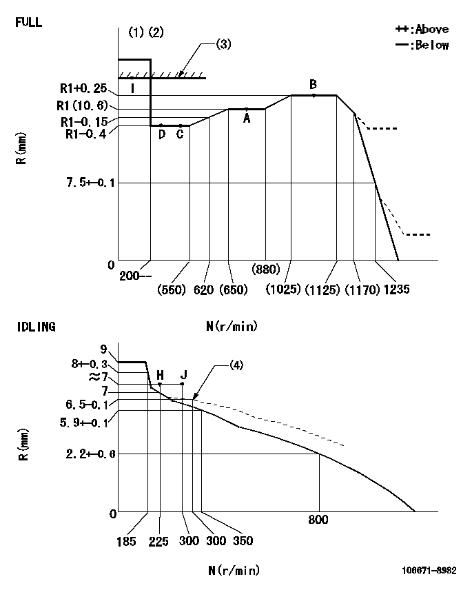
N:Pump speed
R:Rack position (mm)
(1)Torque cam stamping: T1
(2)Tolerance for racks not indicated: +-0.05mm.
(3)RACK LIMIT
(4)Damper spring setting
----------
T1=AE36
----------
----------
T1=AE36
----------
Speed control lever angle

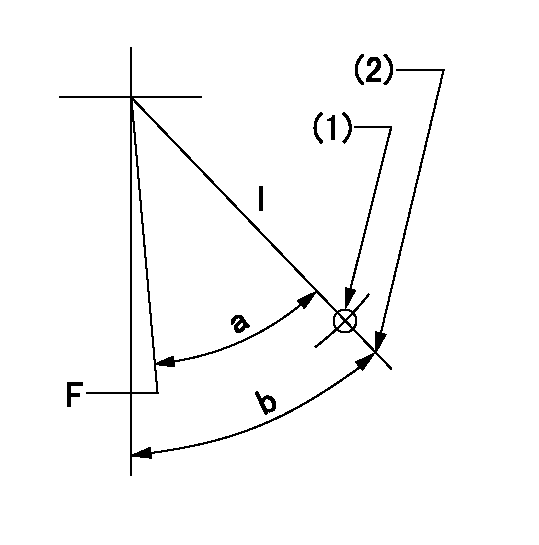
F:Full speed
I:Idle
(1)Use the hole at R = aa
(2)Stopper bolt set position 'H'
----------
aa=42.5mm
----------
a=(32.5deg)+-3deg b=36deg+-5deg
----------
aa=42.5mm
----------
a=(32.5deg)+-3deg b=36deg+-5deg
Stop lever angle

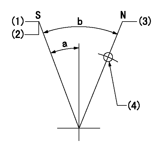
N:Pump normal
S:Stop the pump.
(1)Pump speed aa, rack position bb
(2)Set the stopper screw. (After setting, apply red paint.)
(3)Set the stopper screw at this lever angle.
(4)Use the hole above R = cc
----------
aa=0r/min bb=1.5+-0.3mm cc=30mm
----------
a=22deg+-5deg b=42deg+-5deg
----------
aa=0r/min bb=1.5+-0.3mm cc=30mm
----------
a=22deg+-5deg b=42deg+-5deg
Timing setting

(1)Pump vertical direction
(2)Coupling's key groove position at No 1 cylinder's beginning of injection
(3)-
(4)-
----------
----------
a=(3deg)
----------
----------
a=(3deg)
Information:
System Labeling
The applicant must ensure that identical, legible, and durable labels are affixed on both the diesel emission control strategy and the engine (or an alternate location approved by the Executive Officer) on which the verified diesel emission control strategy is installed except as noted in (3) below. All labels must be constructed and affixed so that the labels resist tampering. All labels must be constructed and affixed so that the labels remain legible for the duration of the diesel emission control strategy minimum warranty period. One label shall be welded, riveted, or otherwise permanently attached to the diesel emission control strategy and the other affixed to the engine in such a manner that the label cannot be easily removed (for example, bolted). The required labels must identify the name, address, and phone number of the manufacturer, the diesel emission control strategy family name (defined in (2) below) of the installed system, a unique serial number, and the month and year of manufacture. The month and year of manufacture are not required on the label if this information can be readily obtained from the applicant by referencing the serial number. The applicant and/or installer must ensure that the label is visible after installation. If the original strategy label is damaged, destroyed, or missing, the device manufacture shall issue an ARB approved replacement. The replacement label must be identical to the original label except for the words "REPLACEMENT LABEL" which must be included at the bottom line of information. A sample scale drawing of the original and replacement labels must be submitted with the verification application. The end user must notify the applicant in the event of a damaged, destroyed, or missing original strategy label. The applicant must issue a replacement label within 45 days of notification by an end user of a damaged, destroyed, or missing label. All labels must be approved by the Executive Officer and must only be used with an ARB verified diesel emission control strategy. Unless an alternative is approved by the Executive Officer, the label information must be in the following format:
1. Name, Address, and Phone Number of Manufacturer
2. Diesel Emission Control Strategy Family Name
3. Product Serial Number
4. (optional) ZZ-ZZ (Month and Year of manufacture, for example, 06-02)
5. Replacement label (Replacement Label to be used only when a replacement of the original label has been issued by the device manufacturer).Diesel Emission Control Strategy Family Name. Each diesel emission control strategy shall be assigned a family name defined as below:Diesel Emission Control Strategy Family Name
Each diesel emission control strategy shall be assigned a family name "CA/MMM/YYY/PM#N##/AP/XXXXX" defined below:CA - Designates a diesel emission control strategy verified in California.YYYY - Manufacturer code (assigned by the executive Officer).PM# - PM verification level 0, 1, 1+, 2, 2+, 3, or 3+ (for example, PM3 means a level 3 PM emission control system).N## - NOx verified reduction level in percent, if any (for example, N25 means NOx reduction of 25 percent).AP - Verified application that includes one of