Information injection-pump assembly
ZEXEL
106671-8981
1066718981
HINO
220009580A
220009580a
Rating:
Service parts 106671-8981 INJECTION-PUMP ASSEMBLY:
1.
_
7.
COUPLING PLATE
8.
_
9.
_
11.
Nozzle and Holder
23600-2950A
12.
Open Pre:MPa(Kqf/cm2)
14.7{150}/21.6{220}
14.
NOZZLE
Include in #1:
106671-8981
as INJECTION-PUMP ASSEMBLY
Cross reference number
ZEXEL
106671-8981
1066718981
HINO
220009580A
220009580a
Zexel num
Bosch num
Firm num
Name
Calibration Data:
Adjustment conditions
Test oil
1404 Test oil ISO4113 or {SAEJ967d}
1404 Test oil ISO4113 or {SAEJ967d}
Test oil temperature
degC
40
40
45
Nozzle and nozzle holder
105780-8140
Bosch type code
EF8511/9A
Nozzle
105780-0000
Bosch type code
DN12SD12T
Nozzle holder
105780-2080
Bosch type code
EF8511/9
Opening pressure
MPa
17.2
Opening pressure
kgf/cm2
175
Injection pipe
Outer diameter - inner diameter - length (mm) mm 8-3-600
Outer diameter - inner diameter - length (mm) mm 8-3-600
Overflow valve
134424-0920
Overflow valve opening pressure
kPa
162
147
177
Overflow valve opening pressure
kgf/cm2
1.65
1.5
1.8
Tester oil delivery pressure
kPa
157
157
157
Tester oil delivery pressure
kgf/cm2
1.6
1.6
1.6
Direction of rotation (viewed from drive side)
Left L
Left L
Injection timing adjustment
Direction of rotation (viewed from drive side)
Left L
Left L
Injection order
1-4-2-6-
3-5
Pre-stroke
mm
4.6
4.54
4.6
Beginning of injection position
Drive side NO.1
Drive side NO.1
Difference between angles 1
Cal 1-4 deg. 60 59.75 60.25
Cal 1-4 deg. 60 59.75 60.25
Difference between angles 2
Cyl.1-2 deg. 120 119.75 120.25
Cyl.1-2 deg. 120 119.75 120.25
Difference between angles 3
Cal 1-6 deg. 180 179.75 180.25
Cal 1-6 deg. 180 179.75 180.25
Difference between angles 4
Cal 1-3 deg. 240 239.75 240.25
Cal 1-3 deg. 240 239.75 240.25
Difference between angles 5
Cal 1-5 deg. 300 299.75 300.25
Cal 1-5 deg. 300 299.75 300.25
Injection quantity adjustment
Adjusting point
-
Rack position
10.6
Pump speed
r/min
700
700
700
Average injection quantity
mm3/st.
113
110
116
Max. variation between cylinders
%
0
-2
2
Basic
*
Fixing the rack
*
Standard for adjustment of the maximum variation between cylinders
*
Injection quantity adjustment_02
Adjusting point
H
Rack position
7+-0.5
Pump speed
r/min
225
225
225
Average injection quantity
mm3/st.
9
6
12
Max. variation between cylinders
%
0
-15
15
Fixing the rack
*
Standard for adjustment of the maximum variation between cylinders
*
Injection quantity adjustment_03
Adjusting point
A
Rack position
R1(10.6)
Pump speed
r/min
700
700
700
Average injection quantity
mm3/st.
113
111
115
Basic
*
Fixing the lever
*
Injection quantity adjustment_04
Adjusting point
B
Rack position
R1+0.25
Pump speed
r/min
1075
1075
1075
Average injection quantity
mm3/st.
121.5
115.5
127.5
Fixing the lever
*
Injection quantity adjustment_05
Adjusting point
I
Rack position
-
Pump speed
r/min
100
100
100
Average injection quantity
mm3/st.
165
165
185
Fixing the lever
*
Rack limit
*
Timer adjustment
Pump speed
r/min
750-50
Advance angle
deg.
0.3
Timer adjustment_02
Pump speed
r/min
1075-50
Advance angle
deg.
5.5
5.2
5.8
Remarks
Finish
Finish
Test data Ex:
Governor adjustment
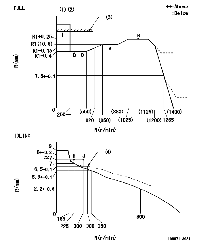
N:Pump speed
R:Rack position (mm)
(1)Torque cam stamping: T1
(2)Tolerance for racks not indicated: +-0.05mm.
(3)RACK LIMIT
(4)Damper spring setting
----------
T1=AE36
----------
----------
T1=AE36
----------
Speed control lever angle
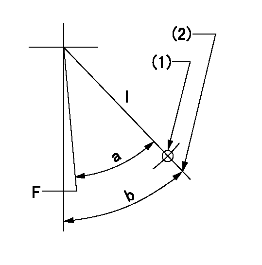
F:Full speed
I:Idle
(1)Use the hole at R = aa
(2)Stopper bolt set position 'H'
----------
aa=42.5mm
----------
a=34deg+-3deg b=36deg+-5deg
----------
aa=42.5mm
----------
a=34deg+-3deg b=36deg+-5deg
Stop lever angle
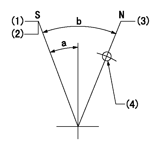
N:Pump normal
S:Stop the pump.
(1)Pump speed aa, rack position bb
(2)Set the stopper screw. (After setting, apply red paint.)
(3)Set the stopper screw at this lever angle.
(4)Use the hole above R = cc
----------
aa=0r/min bb=1.5+-0.3mm cc=30mm
----------
a=22deg+-5deg b=42deg+-5deg
----------
aa=0r/min bb=1.5+-0.3mm cc=30mm
----------
a=22deg+-5deg b=42deg+-5deg
Timing setting

(1)Pump vertical direction
(2)Coupling's key groove position at No 1 cylinder's beginning of injection
(3)-
(4)-
----------
----------
a=(3deg)
----------
----------
a=(3deg)
Information:
Caterpillar Warranty Coverage
Caterpillar warrants the DPF according to the time periods, whichever comes first. Refer to table
Table 1
Engine Type Engine Size Minimum Warranty Period
Off Road (1) Under 25 hp, and for constant speed engines rated under 50 hp with rated speeds greater than or equal to 3,000 RPM 3 years or 1,600 hours
At or above 25 hp and under 50 hp 4 years or 2,600 hours
At or above 50 hp 5 years or 4,200 hours
( 1 ) Includes portable engines, stationary, marine, locomotives, TRU, and APU.If any emission-related part of your diesel emission control system is defective in design, materials, workmanship, or operation of the diesel emission control system thus causing the diesel emission control system to fail to conform to the emission control performance level the diesel emission control system was verified to, or to the requirements in the "California Code of Regulations Title 13 Sections 2700 to 2706 and 2710", within the warranty period, as defined above, Caterpillar will repair or replace the diesel emission control system, including parts and labor.In addition, Caterpillar will replace or repair the engine components to the condition prior to the failure, including parts and labor, for damage to the engine proximately caused by the verified diesel emission control strategy. This warranty also includes those relevant diagnostic expenses in the case in which a warranty claim is valid. Caterpillar may, instead pay the fair market value of the engine prior to the time the failure occurs.Owner Warranty Responsibility
As the (vehicle, engine, equipment) owner, you are responsible for performing the required maintenance described in your owners manual. Caterpillar recommends that you retain all maintenance records and receipts for maintenance expenses for your vehicle, engine, or equipment, and diesel emission control system. If you do not keep your receipts or fail to perform all scheduled maintenance, Caterpillar may have grounds to deny warranty coverage. You are responsible for presenting your vehicle, equipment, or engine, and diesel emission control system to a (applicant name) dealer as soon as a problem is detected. The warranty repair or replacement should be completed in a reasonable amount of time, not to exceed 30 days. If a replacement is needed, this process may be extended to 90 days should a replacement not be available, but must be performed as soon as a replacement becomes available.If you have questions regarding your warranty rights and responsibilities, contact (Insert chosen applicant contact) at:California Air Resources Board
9528 Telstar Avenue
El Monte, CA 91731
helpline@arb.ca.gov.
1-877-CAT-0909800-363-7664Refer to Special Instruction, REHS9213, "Caterpillar Post Installation Compatibility Assessment for Stationary Engines" and Special Instructions, REHS9214, "Post Installation Compatibility Assessment for NEW Stationary Engines".Register warranty per Caterpillar form Special Instruction, REHS5097, "Instructions to Register the Retrofit and Submit Service Reporting {1000, 3000, 7000, 7570}"Maintain all records of installation, pictures, warranty claims, and PICA Form. Provide training for all operation and maintenance.