Information injection-pump assembly
BOSCH
9 400 610 899
9400610899
ZEXEL
106671-8971
1066718971
Rating:
Service parts 106671-8971 INJECTION-PUMP ASSEMBLY:
1.
_
7.
COUPLING PLATE
8.
_
9.
_
11.
Nozzle and Holder
23600-2030A
12.
Open Pre:MPa(Kqf/cm2)
19.6{200}
15.
NOZZLE SET
Include in #1:
106671-8971
as INJECTION-PUMP ASSEMBLY
Cross reference number
BOSCH
9 400 610 899
9400610899
ZEXEL
106671-8971
1066718971
Zexel num
Bosch num
Firm num
Name
Calibration Data:
Adjustment conditions
Test oil
1404 Test oil ISO4113 or {SAEJ967d}
1404 Test oil ISO4113 or {SAEJ967d}
Test oil temperature
degC
40
40
45
Nozzle and nozzle holder
105780-8140
Bosch type code
EF8511/9A
Nozzle
105780-0000
Bosch type code
DN12SD12T
Nozzle holder
105780-2080
Bosch type code
EF8511/9
Opening pressure
MPa
17.2
Opening pressure
kgf/cm2
175
Injection pipe
Outer diameter - inner diameter - length (mm) mm 8-3-600
Outer diameter - inner diameter - length (mm) mm 8-3-600
Overflow valve
134424-0920
Overflow valve opening pressure
kPa
162
147
177
Overflow valve opening pressure
kgf/cm2
1.65
1.5
1.8
Tester oil delivery pressure
kPa
157
157
157
Tester oil delivery pressure
kgf/cm2
1.6
1.6
1.6
Direction of rotation (viewed from drive side)
Left L
Left L
Injection timing adjustment
Direction of rotation (viewed from drive side)
Left L
Left L
Injection order
1-4-2-6-
3-5
Pre-stroke
mm
3.3
3.2
3.3
Beginning of injection position
Drive side NO.1
Drive side NO.1
Difference between angles 1
Cal 1-4 deg. 60 59.5 60.5
Cal 1-4 deg. 60 59.5 60.5
Difference between angles 2
Cyl.1-2 deg. 120 119.5 120.5
Cyl.1-2 deg. 120 119.5 120.5
Difference between angles 3
Cal 1-6 deg. 180 179.5 180.5
Cal 1-6 deg. 180 179.5 180.5
Difference between angles 4
Cal 1-3 deg. 240 239.5 240.5
Cal 1-3 deg. 240 239.5 240.5
Difference between angles 5
Cal 1-5 deg. 300 299.5 300.5
Cal 1-5 deg. 300 299.5 300.5
Injection quantity adjustment
Adjusting point
A
Rack position
9.4
Pump speed
r/min
900
900
900
Average injection quantity
mm3/st.
188.5
186.5
190.5
Max. variation between cylinders
%
0
-4
4
Basic
*
Fixing the rack
*
Boost pressure
kPa
107
107
Boost pressure
mmHg
800
800
Injection quantity adjustment_02
Adjusting point
B
Rack position
9
Pump speed
r/min
750
750
750
Average injection quantity
mm3/st.
170
167
173
Max. variation between cylinders
%
0
-4
4
Fixing the rack
*
Boost pressure
kPa
107
107
Boost pressure
mmHg
800
800
Injection quantity adjustment_03
Adjusting point
D
Rack position
4.7+-0.5
Pump speed
r/min
360
360
360
Average injection quantity
mm3/st.
9.5
6.5
12.5
Max. variation between cylinders
%
0
-15
15
Fixing the rack
*
Boost pressure
kPa
0
0
0
Boost pressure
mmHg
0
0
0
Boost compensator adjustment
Pump speed
r/min
550
550
550
Rack position
R1-0.8
Boost pressure
kPa
66.7
66.7
66.7
Boost pressure
mmHg
500
500
500
Boost compensator adjustment_02
Pump speed
r/min
550
550
550
Rack position
R1(11.3)
Boost pressure
kPa
93.3
86.6
100
Boost pressure
mmHg
700
650
750
Timer adjustment
Pump speed
r/min
850--
Advance angle
deg.
0
0
0
Remarks
Start
Start
Timer adjustment_02
Pump speed
r/min
800
Advance angle
deg.
0.5
Timer adjustment_03
Pump speed
r/min
900
Advance angle
deg.
0.5
0
1
Timer adjustment_04
Pump speed
r/min
-
Advance angle
deg.
1.5
1.5
1.5
Remarks
Measure the actual speed, stop
Measure the actual speed, stop
Test data Ex:
Governor adjustment
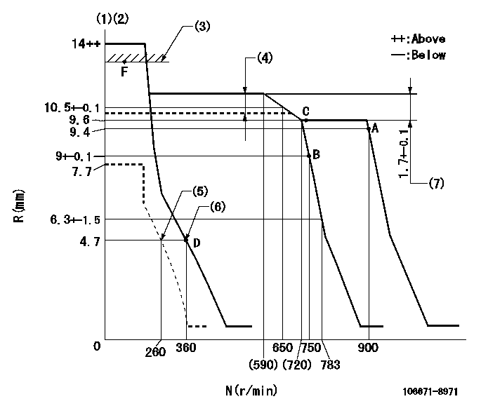
N:Pump speed
R:Rack position (mm)
(1)Notch fixed: K
(2)Tolerance for racks not indicated: +-0.05mm.
(3)Boost compensator excessive fuel lever at operation (at 0 boost pressure): L1
(4)Boost compensator stroke: BCL
(5)Set idle sub-spring
(6)Main spring setting
(7)Rack difference between N = N1 and N = N2
----------
K=6 L1=13+-0.1mm BCL=0.8+-0.05mm N1=750r/min N2=550r/min
----------
----------
K=6 L1=13+-0.1mm BCL=0.8+-0.05mm N1=750r/min N2=550r/min
----------
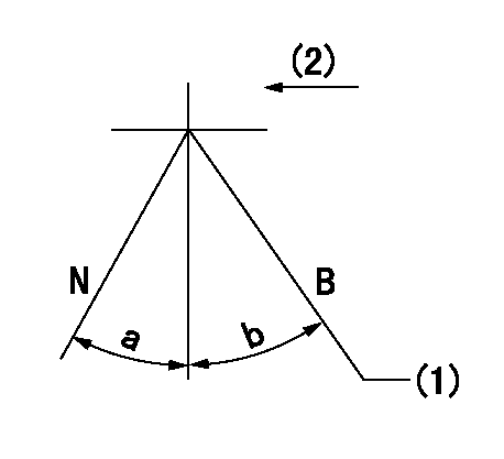
Speed control lever angle
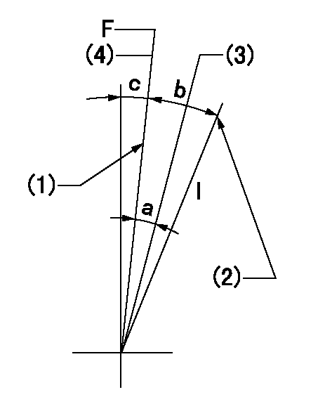
F:Full speed
I:Idle
(1)Stopper bolt setting
(2)Stopper bolt setting
(3)When pump speed set at aa
(4)Set the pump speed at bb (at delivery)
----------
aa=750r/min bb=900r/min
----------
a=(5deg)+-5deg b=(20deg)+-5deg c=(3deg)+-5deg
----------
aa=750r/min bb=900r/min
----------
a=(5deg)+-5deg b=(20deg)+-5deg c=(3deg)+-5deg
Stop lever angle
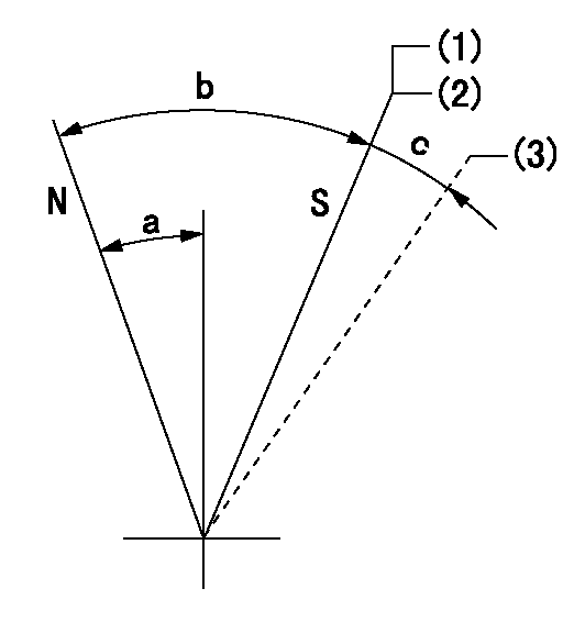
N:Pump normal
S:Stop the pump.
(1)Contacts inner stopper.
(2)Rack position aa or less, pump speed bb
(3)Contacts outer stopper.
----------
aa=4.2mm bb=0r/min
----------
a=27deg+-5deg b=53deg+-5deg c=(11deg)
----------
aa=4.2mm bb=0r/min
----------
a=27deg+-5deg b=53deg+-5deg c=(11deg)
0000001101
N:Normal
B:When boosted
(1)Rack position = aa at boost pressure 0.
(2)Drive side
----------
aa=13+-0.1mm
----------
a=(15deg) b=(13deg)
----------
aa=13+-0.1mm
----------
a=(15deg) b=(13deg)
Timing setting

(1)Pump vertical direction
(2)Coupling's key groove position at No 1 cylinder's beginning of injection
(3)-
(4)-
----------
----------
a=(0deg)
----------
----------
a=(0deg)
Information:
Illustration 6 g06375966
Current hose routing
(E) 3U-2752 Clip
Illustration 7 g06375968
(D3) 32.31 mm (1.272 inch)
(D4) 80.00 mm (3.150 inch)
(1) 178-7023 Boss
Illustration 8 g06375967
New hose routing
(1) 178-7023 Boss
(2) 420-5299 Clip
Remove clip (E) and install boss (1) per the dimensions and secure the hose using two double clips (2), as shown in Illustration 6, Illustration 7, and Illustration 8.Changes to CEM Line Routing for 730C2, 730C2 EJ, 730, and 735 Articulated Trucks
Illustration 9 g06376002
Current hose routing
(F) 421-9627 Bracket As
(G) 3U-2752 Clip
(H) 7K-1181 Cable Strap
Remove bracket assembly (F), clips (G), strap cable (H), and other mounting hardware, as shown in Illustration 9.
Illustration 10 g06376255
New hose routing
(2) 420-5299 Clip
Install two double clips (2) as shown in Illustration 10.Note: The hose routing simplifies the installation and provides additional clearance to the oil gallery on the right-hand side of the machine.Changes to DEF cooling Lines Routing (To/From Tank) for all High Regulated Countries (HRC) Machines
Illustration 11 g06376256
Current hose routing
(J) 312-0288 Clamp
Illustration 12 g06376257
New hose routing
(3) 520-7003 ClampRemove old clamps (J) and replace with the new clamps (3), as shown in Illustration 11 and Illustration 12.Changes to DEF Cooling Lines Routing (To Pump- Both ends) for all HRC Machines
Illustration 13 g06376263
Current clamp
(J) 312-0288 Clamp
Illustration 14 g06376264
New clamp
(3) 520-7003 Clamp
Illustration 15 g06376266
Current clamp
(J) 312-0288 Clamp
Illustration 16 g06376267
New clamp
(3) 520-7003 ClampRemove old clamps (J) and replace with the new clamps (3), as shown in Illustration 13, Illustration 14, Illustration 15, and Illustration 16.Changes to DEF Cooling Lines (From Pump- Both ends) Routing for all HRC Machines
Illustration 17 g06376285
Current clamp
(K) 433-0933 Clamp
Illustration 18 g06376288
New clamp
(4) 520-7002 ClampRemove existing clamps (K) and replace with the new clamps (4), as shown in Illustration 17 and Illustration 18.