Information injection-pump assembly
ZEXEL
106671-8970
1066718970
HINO
220204920A
220204920a
Rating:
Service parts 106671-8970 INJECTION-PUMP ASSEMBLY:
1.
_
7.
COUPLING PLATE
8.
_
9.
_
11.
Nozzle and Holder
23600-2030A
12.
Open Pre:MPa(Kqf/cm2)
19.6{200}
15.
NOZZLE SET
Include in #1:
106671-8970
as INJECTION-PUMP ASSEMBLY
Cross reference number
ZEXEL
106671-8970
1066718970
HINO
220204920A
220204920a
Zexel num
Bosch num
Firm num
Name
Calibration Data:
Adjustment conditions
Test oil
1404 Test oil ISO4113 or {SAEJ967d}
1404 Test oil ISO4113 or {SAEJ967d}
Test oil temperature
degC
40
40
45
Nozzle and nozzle holder
105780-8140
Bosch type code
EF8511/9A
Nozzle
105780-0000
Bosch type code
DN12SD12T
Nozzle holder
105780-2080
Bosch type code
EF8511/9
Opening pressure
MPa
17.2
Opening pressure
kgf/cm2
175
Injection pipe
Outer diameter - inner diameter - length (mm) mm 8-3-600
Outer diameter - inner diameter - length (mm) mm 8-3-600
Overflow valve
134424-0920
Overflow valve opening pressure
kPa
162
147
177
Overflow valve opening pressure
kgf/cm2
1.65
1.5
1.8
Tester oil delivery pressure
kPa
157
157
157
Tester oil delivery pressure
kgf/cm2
1.6
1.6
1.6
Direction of rotation (viewed from drive side)
Left L
Left L
Injection timing adjustment
Direction of rotation (viewed from drive side)
Left L
Left L
Injection order
1-4-2-6-
3-5
Pre-stroke
mm
3.3
3.2
3.3
Beginning of injection position
Drive side NO.1
Drive side NO.1
Difference between angles 1
Cal 1-4 deg. 60 59.5 60.5
Cal 1-4 deg. 60 59.5 60.5
Difference between angles 2
Cyl.1-2 deg. 120 119.5 120.5
Cyl.1-2 deg. 120 119.5 120.5
Difference between angles 3
Cal 1-6 deg. 180 179.5 180.5
Cal 1-6 deg. 180 179.5 180.5
Difference between angles 4
Cal 1-3 deg. 240 239.5 240.5
Cal 1-3 deg. 240 239.5 240.5
Difference between angles 5
Cal 1-5 deg. 300 299.5 300.5
Cal 1-5 deg. 300 299.5 300.5
Injection quantity adjustment
Adjusting point
A
Rack position
9.4
Pump speed
r/min
900
900
900
Average injection quantity
mm3/st.
188.5
186.5
190.5
Max. variation between cylinders
%
0
-4
4
Basic
*
Fixing the rack
*
Boost pressure
kPa
131
131
Boost pressure
mmHg
980
980
Injection quantity adjustment_02
Adjusting point
B
Rack position
9
Pump speed
r/min
750
750
750
Average injection quantity
mm3/st.
170
167
173
Max. variation between cylinders
%
0
-4
4
Fixing the rack
*
Boost pressure
kPa
131
131
Boost pressure
mmHg
980
980
Injection quantity adjustment_03
Adjusting point
D
Rack position
4.7+-0.5
Pump speed
r/min
360
360
360
Average injection quantity
mm3/st.
9.5
6.5
12.5
Max. variation between cylinders
%
0
-15
15
Fixing the rack
*
Boost pressure
kPa
0
0
0
Boost pressure
mmHg
0
0
0
Boost compensator adjustment
Pump speed
r/min
550
550
550
Rack position
7.9
Boost pressure
kPa
66.7
66.7
66.7
Boost pressure
mmHg
500
500
500
Boost compensator adjustment_02
Pump speed
r/min
550
550
550
Rack position
9.6
Boost pressure
kPa
93.3
90
93.3
Boost pressure
mmHg
700
675
700
Boost compensator adjustment_03
Pump speed
r/min
550
550
550
Rack position
(11.3)
Boost pressure
kPa
117
117
117
Boost pressure
mmHg
880
880
880
Timer adjustment
Pump speed
r/min
850--
Advance angle
deg.
0
0
0
Remarks
Start
Start
Timer adjustment_02
Pump speed
r/min
800
Advance angle
deg.
0.5
Timer adjustment_03
Pump speed
r/min
900
Advance angle
deg.
0.5
0
1
Timer adjustment_04
Pump speed
r/min
-
Advance angle
deg.
1.5
1.5
1.5
Remarks
Measure the actual speed, stop
Measure the actual speed, stop
Test data Ex:
Governor adjustment
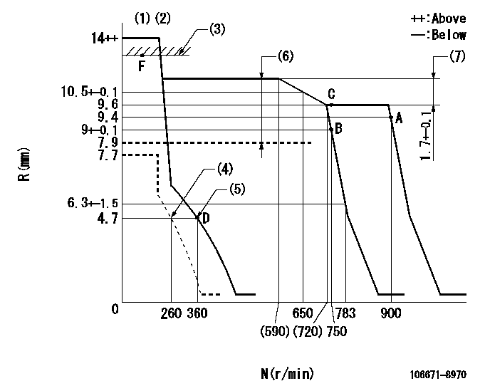
N:Pump speed
R:Rack position (mm)
(1)Notch fixed: K
(2)Tolerance for racks not indicated: +-0.05mm.
(3)Excessive fuel lever setting (boost pressure 0)
(4)Set idle sub-spring
(5)Main spring setting
(6)Boost compensator stroke: BCL
(7)Rack difference between N = N1 and N = N2
----------
K=6 BCL=(3.4)mm N1=750r/min N2=550r/min
----------
----------
K=6 BCL=(3.4)mm N1=750r/min N2=550r/min
----------
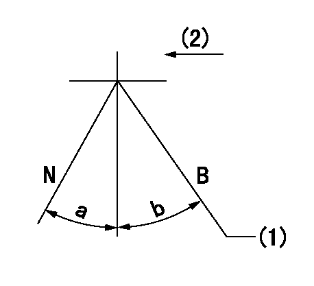
Speed control lever angle
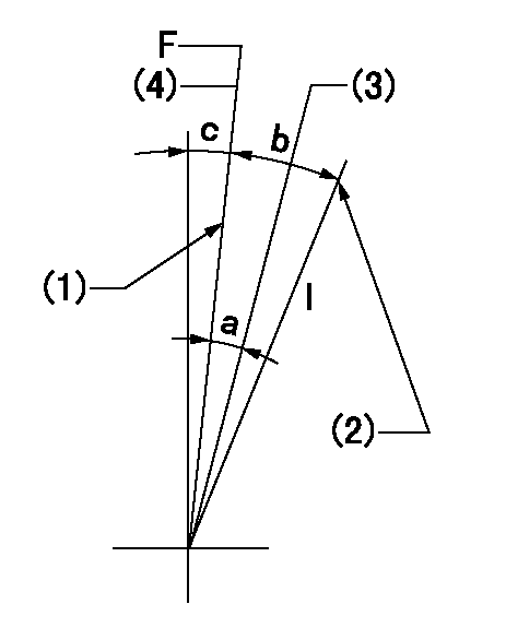
F:Full speed
I:Idle
(1)Stopper bolt setting
(2)Stopper bolt setting
(3)When pump speed set at aa
(4)Set the pump speed at bb (at delivery)
----------
aa=750r/min bb=900r/min
----------
a=5deg+-5deg b=20deg+-5deg c=3deg+-5deg
----------
aa=750r/min bb=900r/min
----------
a=5deg+-5deg b=20deg+-5deg c=3deg+-5deg
Stop lever angle
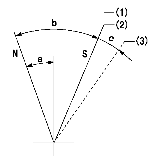
N:Pump normal
S:Stop the pump.
(1)Contacts inner stopper.
(2)Rack position aa or less, pump speed bb
(3)Contacts outer stopper.
----------
aa=4.2mm bb=0r/min
----------
a=27deg+-5deg b=53deg+-5deg c=(11deg)
----------
aa=4.2mm bb=0r/min
----------
a=27deg+-5deg b=53deg+-5deg c=(11deg)
0000001101
N:Normal
B:When boosted
(1)Rack position = aa at boost pressure 0.
(2)Drive side
----------
aa=13+-0.1mm
----------
a=(15deg) b=(13deg)
----------
aa=13+-0.1mm
----------
a=(15deg) b=(13deg)
Timing setting

(1)Pump vertical direction
(2)Coupling's key groove position at No 1 cylinder's beginning of injection
(3)-
(4)-
----------
----------
a=(0deg)
----------
----------
a=(0deg)
Information:
Cleaning the DPF
Because the sections of the DPF are replaceable, a small stock of filter sections can be maintained. Filter sections from a small on-hand stock can be used to replace filters in service at the next scheduled cleaning. The removed filters can be cleaned and returned for installation in the next vehicle. This process of maintaining a stock of filter sections can significantly reduce the amount of down time that will occur.Note: Check State and Local air pollution regulations pertaining to record keeping of serviced filters. Some governmental entities may require filter tracking. Note: Perform a back pressure test prior to cleaning the DPF and record the results. After cleaning the DPF, run the engine at high idle for 5 to 15 minutes to bring the engine and exhaust system to operating temperature. Perform another back pressure test and record the results on the DPF cleaning records form.
Weigh and record the filter unit prior to baking.
By baking the filter under a controlled procedure, the remaining soot on the DPF will burn off and leave a smaller quantity of ash. Failure to observe this procedure can result to damage or cracking to the DPF substrate. A commercial programmable oven is required for this procedure. Careful adherence to this procedure is imperative. Deviation from this procedure may lead to thermal shock and cracking of the DPF substrate or melting at high temperatures.
Place filter into a programmable commercial oven designed for this purpose. Center the filter as much as possible on a rack with 2 inches of spacing below and above for best results.
Program the oven as follows:
Ramp oven temperature to 200° C (392° F)
Hold oven temperature at 200° C (392° F)
Ramp oven temperature to 450° C (842° F)
Hold oven temperature at 450° C (842° F)
Cool down to ambient temperature at natural rate within the oven with the doors closed. Do not use fans.
Place filter in cleaning machine and clean as per machine instructions.
Replace the filter in the oven. Ramp to 650° C (1202° F) in 60 minutes.
Hold oven temperature at 650° C (1202° F) for 240 minutes.
Cool to ambient temperature at a natural rate. Do not use fans.Note: Allow the filter to cool in the oven with the door closed until the filter can be handled with bare hands.Cleaning Procedure
Ash and soot should be removed from the DPF utilizing the Cat 319-2189 Diesel Particulate Filter Cleaner Gp. Using the cleaner without following baking procedure, results in lower efficiency cleaning and will reduce the life of the HEPA filters in the machine. The tool uses pulsed air to flush the ash and soot.Note: Other cleaning methods can release significant quantities of airborne ash and soot. Airborne ash and soot should not be inhaled and may be regulated as a hazardous substance by local regulations.Cleaned Filter Specification
The following steps determine if the DPF was properly cleaned:Note: This specification applies to filters that were cleaned of ash only. This specification is only valid subsequent to the recommend