Information injection-pump assembly
BOSCH
9 400 617 027
9400617027
ZEXEL
106671-8882
1066718882
HINO
220801722B
220801722b
Rating:
Cross reference number
BOSCH
9 400 617 027
9400617027
ZEXEL
106671-8882
1066718882
HINO
220801722B
220801722b
Zexel num
Bosch num
Firm num
Name
106671-8882
9 400 617 027
220801722B HINO
INJECTION-PUMP ASSEMBLY
K13C-TK K
K13C-TK K
Calibration Data:
Adjustment conditions
Test oil
1404 Test oil ISO4113 or {SAEJ967d}
1404 Test oil ISO4113 or {SAEJ967d}
Test oil temperature
degC
40
40
45
Nozzle and nozzle holder
105780-8140
Bosch type code
EF8511/9A
Nozzle
105780-0000
Bosch type code
DN12SD12T
Nozzle holder
105780-2080
Bosch type code
EF8511/9
Opening pressure
MPa
17.2
Opening pressure
kgf/cm2
175
Injection pipe
Outer diameter - inner diameter - length (mm) mm 8-3-600
Outer diameter - inner diameter - length (mm) mm 8-3-600
Overflow valve
134424-4420
Overflow valve opening pressure
kPa
162
147
177
Overflow valve opening pressure
kgf/cm2
1.65
1.5
1.8
Tester oil delivery pressure
kPa
157
157
157
Tester oil delivery pressure
kgf/cm2
1.6
1.6
1.6
Direction of rotation (viewed from drive side)
Left L
Left L
Injection timing adjustment
Direction of rotation (viewed from drive side)
Left L
Left L
Injection order
1-4-2-6-
3-5
Pre-stroke
mm
3.9
3.84
3.9
Beginning of injection position
Drive side NO.1
Drive side NO.1
Difference between angles 1
Cal 1-4 deg. 60 59.75 60.25
Cal 1-4 deg. 60 59.75 60.25
Difference between angles 2
Cyl.1-2 deg. 120 119.75 120.25
Cyl.1-2 deg. 120 119.75 120.25
Difference between angles 3
Cal 1-6 deg. 180 179.75 180.25
Cal 1-6 deg. 180 179.75 180.25
Difference between angles 4
Cal 1-3 deg. 240 239.75 240.25
Cal 1-3 deg. 240 239.75 240.25
Difference between angles 5
Cal 1-5 deg. 300 299.75 300.25
Cal 1-5 deg. 300 299.75 300.25
Injection quantity adjustment
Adjusting point
A
Rack position
9.9
Pump speed
r/min
550
550
550
Average injection quantity
mm3/st.
189.5
187.5
191.5
Max. variation between cylinders
%
0
-2
2
Basic
*
Fixing the lever
*
Boost pressure
kPa
53.3
53.3
Boost pressure
mmHg
400
400
Injection quantity adjustment_02
Adjusting point
B
Rack position
9.45
Pump speed
r/min
1000
1000
1000
Average injection quantity
mm3/st.
169.5
166.5
172.5
Max. variation between cylinders
%
0
-5
5
Fixing the lever
*
Boost pressure
kPa
53.3
53.3
Boost pressure
mmHg
400
400
Injection quantity adjustment_03
Adjusting point
D
Rack position
3.5+-0.5
Pump speed
r/min
250
250
250
Average injection quantity
mm3/st.
10.5
7.5
13.5
Max. variation between cylinders
%
0
-15
15
Fixing the rack
*
Boost pressure
kPa
0
0
0
Boost pressure
mmHg
0
0
0
Injection quantity adjustment_04
Adjusting point
E
Rack position
-
Pump speed
r/min
100
100
100
Average injection quantity
mm3/st.
200
195
205
Fixing the lever
*
Boost pressure
kPa
53.3
53.3
Boost pressure
mmHg
400
400
Rack limit
*
Injection quantity adjustment_05
Adjusting point
H
Rack position
-
Pump speed
r/min
100
100
100
Average injection quantity
mm3/st.
110
110
Fixing the lever
*
Boost pressure
kPa
0
0
0
Boost pressure
mmHg
0
0
0
Boost compensator adjustment
Pump speed
r/min
550
550
550
Rack position
(7.8)
Boost pressure
kPa
13.3
13.3
15.3
Boost pressure
mmHg
100
100
115
Boost compensator adjustment_02
Pump speed
r/min
550
550
550
Rack position
9.9
Boost pressure
kPa
40
40
40
Boost pressure
mmHg
300
300
300
Timer adjustment
Pump speed
r/min
700--
Advance angle
deg.
0
0
0
Remarks
Start
Start
Timer adjustment_02
Pump speed
r/min
650
Advance angle
deg.
0.5
Timer adjustment_03
Pump speed
r/min
1000
Advance angle
deg.
4
3.7
4.3
Remarks
Finish
Finish
Test data Ex:
Governor adjustment
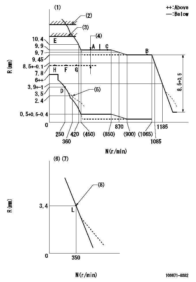
N:Pump speed
R:Rack position (mm)
(1)Tolerance for racks not indicated: +-0.05mm.
(2)Stop lever setting: R1
(3)RACK LIMIT
(4)Boost compensator stroke: BCL
(5)Damper spring setting
(6)Variable speed specification: idling adjustment
(7)Fix the lever at the full-load position at delivery.
(8)Main spring setting
----------
R1=(12.1)+0.5mm BCL=(2.1)mm
----------
----------
R1=(12.1)+0.5mm BCL=(2.1)mm
----------
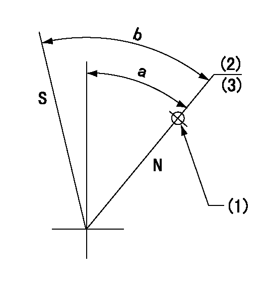
Speed control lever angle
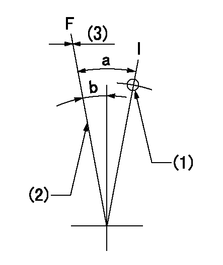
F:Full speed
I:Idle
(1)Use the hole at R = aa
(2)Stopper bolt setting
(3)Set the stopper bolt (fixed at full-load position at delivery.)
----------
aa=130mm
----------
a=(13deg)+-5deg b=(1deg)+-5deg
----------
aa=130mm
----------
a=(13deg)+-5deg b=(1deg)+-5deg
0000000901
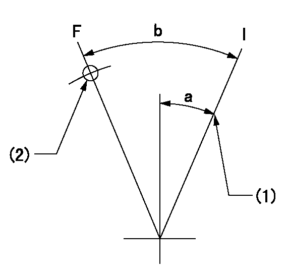
F:Full load
I:Idle
(1)Stopper bolt setting
(2)Use the hole at R = aa
----------
aa=50mm
----------
a=25deg+-5deg b=34.5deg+-3deg
----------
aa=50mm
----------
a=25deg+-5deg b=34.5deg+-3deg
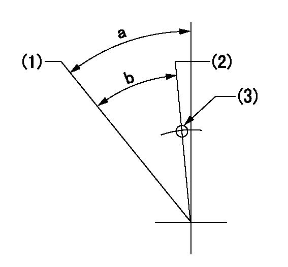
Stop lever angle
N:Pump normal
S:Stop the pump.
(1)Use the hole at R = aa
(2)Set the rack position at bb before adjusting the governor
(3)Set the stopper screw. (After setting, apply red paint.)
----------
aa=36mm bb=(12.1)+0.5mm
----------
a=35deg+-5deg b=39deg+-5deg
----------
aa=36mm bb=(12.1)+0.5mm
----------
a=35deg+-5deg b=39deg+-5deg
0000001201
(1)Minimum - maximum speed specification
(2)Variable speed specification
(3)Use the hole at R = aa
----------
aa=112mm
----------
a=(18.5deg)+-5deg b=(16.5deg)
----------
aa=112mm
----------
a=(18.5deg)+-5deg b=(16.5deg)
0000001501 LEVER

2-stage changeover lever adjustment
(A) Speed lever
(B) Load lever
(C) 2-stage changeover lever
(D) Link
(E) Bolt
(G) Variable speed specifications
(H) Minimum maximum speed specifications
F:Full speed
I:Idle
1. Minimum-maximum speed specification adjustment (when running)
(1)After completing governor adjustment, hold the 2-stage changeover lever (C) so that the speed lever (A) contacts the full speed stopper.
(2)In this condition, the load lever is held in the idle position.
(3)Adjust bolt (E) so that the clearance between the pin underneath lever (C) and the end of the long groove in link (D) is L.
(4)Lock using the nut.
2. Variable speed specification adjustment (at operation)
(1)Hold the 2-stage changeover lever (C) so that the load lever (B) contacts the full load stopper. (When the load lever is equipped with a cancel mechanism, move it so that it contacts the stopper without canceling.)
(2)In this condition, confirm that the speed lever (A) moves from idle to full speed.
----------
----------
----------
----------
0000001601 ACS
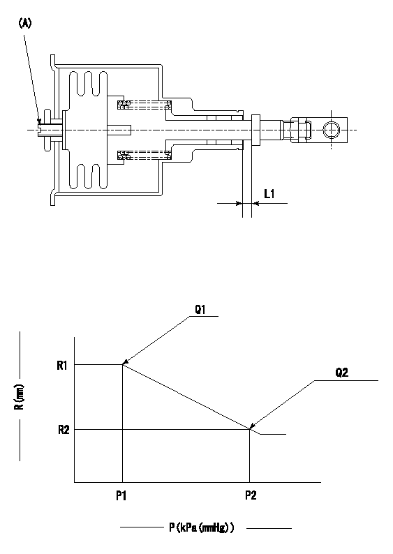
(A) Set screw
1. Aneroid compensator unit adjustment
Screw in (A) to obtain L1.
2. Adjustment following governor installation
(1)Set the speed of the pump to N1 r/min and fix the control lever at the full set position.
(2)Screw in the aneroid compensator to obtain the performance shown in the graph above.
----------
N1=1000r/min L1=0.1~0.5mm
----------
R1=9.45mm R2=8.7mm P1=(84.2)kPa((632)mmHg) P2=64+-0.7kPa(480+-5mmHg) Q1=169.5+-3cm3/1000st Q2=(146)+-3cm3/1000st
----------
N1=1000r/min L1=0.1~0.5mm
----------
R1=9.45mm R2=8.7mm P1=(84.2)kPa((632)mmHg) P2=64+-0.7kPa(480+-5mmHg) Q1=169.5+-3cm3/1000st Q2=(146)+-3cm3/1000st
Timing setting

(1)Pump vertical direction
(2)Coupling's key groove position at No 1 cylinder's beginning of injection
(3)-
(4)-
----------
----------
a=(0deg)
----------
----------
a=(0deg)
Information:
Use of Cat Diesel Fuel System Cleaner or Cat Diesel Fuel System Conditioner does not lessen the responsibility of the engine owner and/or responsibility of the fuel supplier to follow all industry standard maintenance practices for fuel storage and for fuel handling. Refer to the “General Fuel Information” article in this Special Publication for additional information. Additionally, use of Cat Diesel Fuel System Cleaner or Cat Diesel Fuel System Conditioner does NOT lessen the responsibility of the owner of the engine to use appropriate diesel fuel. Refer to the “Fuel Specifications” section in this Special Publication (Maintenance Section) for guidance.
Caterpillar strongly recommends that Cat Diesel Fuel System Cleaner be used with biodiesel and biodiesel blends. Cat Diesel Fuel System Cleaner is suitable for use with biodiesel/biodiesel blends that meet Cat biodiesel recommendations and requirements. Note that not all fuel cleaners are suitable for use with biodiesel/biodiesel blends. Read and follow all applicable label usage instructions. Also, refer to this Special Publication, "Distillate Diesel Fuel", article and also refer to the “Biodiesel” article, which includes Cat biodiesel recommendations and requirements.When used as directed, Cat Diesel Fuel System Cleaner has proven to be compatible with non-road Tier 4 U.S. EPA certified engines that are equipped with aftertreatment devices.Note: When used as directed, Cat Diesel Fuel System Cleaner will not raise fuel sulfur levels measurably in the final fuel/additive blend. Follow all applicable national, regional, and local laws, mandates, and regulations concerning the use of diesel fuel conditioners/additives.
When used as directed Cat Diesel Fuel System Cleaner will not raise fuel sulfur levels measurably in the final fuel/additive blend. But, in the U.S., aftermarket fuel additives (retail consumer level versus bulk fuel additives used at the fuel supplier/distributor level) with more than 15 ppm sulfur are NOT allowed to be used in applications where ULSD usage is mandated (15 ppm or less fuel sulfur). Note that Cat Diesel Fuel System Cleaner contains less than 15 ppm of sulfur and is acceptable for use with ULSD fuel.
Renewable and Alternative Fuels
Renewable fuels are derived from renewable resources such as planted crops and crop residues (referred to as biomass), waste, algae, cellulosic material, yard and food waste, etc. Renewable fuels reduce the carbon footprint of the fuels compared to fossil fuels on a Life Cycle Analysis basis. Caterpillar, through sustainability initiatives, supports the development and use of renewable fuels.Renewable fuels (other than biodiesel) and alternative fuels (such as but not limited to Gas-to-Liquid fuel) are typically >99% hydrocarbons (composed of carbon and hydrogen). An exception is biodiesel, which is an oxygenated renewable fuel. Biodiesel is discussed in a separate article in this Fuel section. Significant research is on going to develop renewable fuels and produce the fuels economically.Caterpillar is not in a position to test all varieties of renewable and alternative fuels that are advertised in the market place. If a renewable or alternative fuel fulfills the performance requirements described in Cat Fuel Specification, the latest version of "ASTM D975", the latest version of "EN
Have questions with 106671-8882?
Group cross 106671-8882 ZEXEL
Hino
Hino
Hino
106671-8882
9 400 617 027
220801722B
INJECTION-PUMP ASSEMBLY
K13C-TK
K13C-TK