Information injection-pump assembly
BOSCH
9 400 617 026
9400617026
ZEXEL
106671-8870
1066718870
HINO
220009290A
220009290a
Rating:
Service parts 106671-8870 INJECTION-PUMP ASSEMBLY:
1.
_
7.
COUPLING PLATE
8.
_
9.
_
11.
Nozzle and Holder
12.
Open Pre:MPa(Kqf/cm2)
21.6(220)

15.
NOZZLE SET
Include in #1:
106671-8870
as INJECTION-PUMP ASSEMBLY
Cross reference number
BOSCH
9 400 617 026
9400617026
ZEXEL
106671-8870
1066718870
HINO
220009290A
220009290a
Zexel num
Bosch num
Firm num
Name
106671-8870
9 400 617 026
220009290A HINO
INJECTION-PUMP ASSEMBLY
K13U K 14CA INJECTION PUMP ASSY PE6P,6PD PE
K13U K 14CA INJECTION PUMP ASSY PE6P,6PD PE
Calibration Data:
Adjustment conditions
Test oil
1404 Test oil ISO4113 or {SAEJ967d}
1404 Test oil ISO4113 or {SAEJ967d}
Test oil temperature
degC
40
40
45
Nozzle and nozzle holder
105780-8140
Bosch type code
EF8511/9A
Nozzle
105780-0000
Bosch type code
DN12SD12T
Nozzle holder
105780-2080
Bosch type code
EF8511/9
Opening pressure
MPa
17.2
Opening pressure
kgf/cm2
175
Injection pipe
Outer diameter - inner diameter - length (mm) mm 8-3-600
Outer diameter - inner diameter - length (mm) mm 8-3-600
Overflow valve
134424-1420
Overflow valve opening pressure
kPa
162
147
177
Overflow valve opening pressure
kgf/cm2
1.65
1.5
1.8
Tester oil delivery pressure
kPa
157
157
157
Tester oil delivery pressure
kgf/cm2
1.6
1.6
1.6
Direction of rotation (viewed from drive side)
Left L
Left L
Injection timing adjustment
Direction of rotation (viewed from drive side)
Left L
Left L
Injection order
1-4-2-6-
3-5
Pre-stroke
mm
3.3
3.2
3.3
Beginning of injection position
Drive side NO.1
Drive side NO.1
Difference between angles 1
Cal 1-4 deg. 60 59.5 60.5
Cal 1-4 deg. 60 59.5 60.5
Difference between angles 2
Cyl.1-2 deg. 120 119.5 120.5
Cyl.1-2 deg. 120 119.5 120.5
Difference between angles 3
Cal 1-6 deg. 180 179.5 180.5
Cal 1-6 deg. 180 179.5 180.5
Difference between angles 4
Cal 1-3 deg. 240 239.5 240.5
Cal 1-3 deg. 240 239.5 240.5
Difference between angles 5
Cal 1-5 deg. 300 299.5 300.5
Cal 1-5 deg. 300 299.5 300.5
Injection quantity adjustment
Adjusting point
A
Rack position
10.6
Pump speed
r/min
500
500
500
Average injection quantity
mm3/st.
128.5
125.5
131.5
Max. variation between cylinders
%
0
-4
4
Fixing the lever
*
Injection quantity adjustment_02
Adjusting point
B
Rack position
10.7
Pump speed
r/min
700
700
700
Average injection quantity
mm3/st.
134.7
132.7
136.7
Max. variation between cylinders
%
0
-2
2
Basic
*
Fixing the lever
*
Injection quantity adjustment_03
Adjusting point
C
Rack position
11.2
Pump speed
r/min
1150
1150
1150
Average injection quantity
mm3/st.
143.7
140.7
146.7
Max. variation between cylinders
%
0
-4
4
Fixing the lever
*
Injection quantity adjustment_04
Adjusting point
D
Rack position
7+-0.5
Pump speed
r/min
225
225
225
Average injection quantity
mm3/st.
15
12
18
Max. variation between cylinders
%
0
-15
15
Fixing the rack
*
Injection quantity adjustment_05
Adjusting point
E
Rack position
-
Pump speed
r/min
100
100
100
Average injection quantity
mm3/st.
126.3
119.3
133.3
Fixing the lever
*
Rack limit
*
Timer adjustment
Pump speed
r/min
950
Advance angle
deg.
0.5
Timer adjustment_02
Pump speed
r/min
1050
Advance angle
deg.
1.7
1.2
2.2
Timer adjustment_03
Pump speed
r/min
1150
Advance angle
deg.
4
3.5
4.5
Remarks
Finish
Finish
Test data Ex:
Governor adjustment
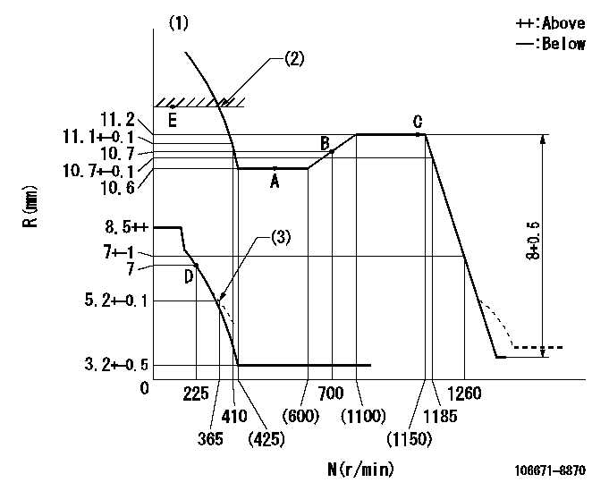
N:Pump speed
R:Rack position (mm)
(1)Tolerance for racks not indicated: +-0.05mm.
(2)RACK LIMIT
(3)Damper spring setting
----------
----------
----------
----------
Speed control lever angle

F:Full speed
----------
----------
a=(14.5deg)+-5deg
----------
----------
a=(14.5deg)+-5deg
0000000901
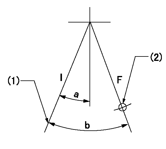
F:Full load
I:Idle
(1)Stopper bolt setting
(2)Use the hole at R = aa
----------
aa=50mm
----------
a=14deg+-5deg b=27.5deg+-3deg
----------
aa=50mm
----------
a=14deg+-5deg b=27.5deg+-3deg
Stop lever angle
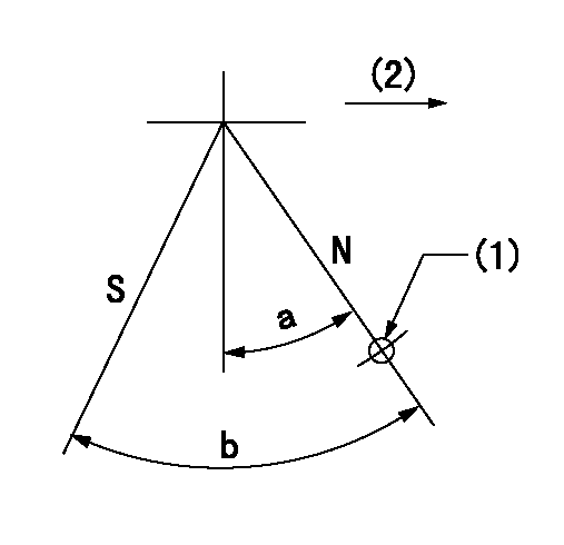
N:Pump normal
S:Stop the pump.
(1)Use the hole at R = aa
(2)Drive side
----------
aa=25mm
----------
a=40deg+-5deg b=64deg+-5deg
----------
aa=25mm
----------
a=40deg+-5deg b=64deg+-5deg
0000001501 GOVERNOR TORQUE CONTROL

Dr:Torque control stroke
(A): Without torque control spring capsule
1. Adjustment procedures
(1)Procedure is the same as that for the RFD (former type), except that the positive torque control stroke must be determined at the full lever setting.
2. Procedures for adjustment
(1)Remove the torque control spring capsule.
(2)Operate the pump at approximately N1. (End of idling spring operation < N1.)
(3)Tilt the lever to the full side.
(4)Set so that R = RF.
(5)Increase the speed by pushing in the screw (attached to the bracket on the rear of the tension lever) through the adjusting window.
(6)Adjust so that the torque control stroke Dr1 can be obtained.
(7)Align N2 and N3 with the torque control spring capsule.
3. Final confirmation
(1)After final confirmation, temporarily set the load lever to N = N1, R = idling position.
(2)From this condition, increase speed to N = N4.
(3)Confirm that positive torque control stroke is Dr2.
----------
N1=500r/min N2=(600)r/min N3=(1100)r/min N4=1100r/min RF=10.6mm Dr1=0.6mm Dr2=0+0.3mm
----------
----------
N1=500r/min N2=(600)r/min N3=(1100)r/min N4=1100r/min RF=10.6mm Dr1=0.6mm Dr2=0+0.3mm
----------
Timing setting

(1)Pump vertical direction
(2)Coupling's key groove position at No 1 cylinder's beginning of injection
(3)-
(4)-
----------
----------
a=(3deg)
----------
----------
a=(3deg)
Information:
Do not operate or work on this product unless you have read and understood the instruction and warnings in the relevant Operation and Maintenance Manuals and relevant service literature. Failure to follow the instructions or heed the warnings could result in injury or death. Proper care is your responsibility.
The following changes are adaptable to machines within the listed serial numbers and are effective with all machines after the listed serial numbers.
Illustration 1 g06325715
View of Air lines group on 966M, 972M, 966M XE, and 972M XE machines
(1) 415-8220 Hose
(2) 8T-6703 Hose Clamp
(3) 211-8073 Protection Cap
Illustration 2 g06325708
View of Air lines group on 980M and 982M machines
(1) 365-0045 Hose
(2) 8T-6703 Hose Clamp
(3) 211-8073 Protection Cap
Table 1
Required Parts
Item Qty New Part Number Part Name Former Part Number
1 1 415-8220 (1) Hose 415-8220
365-0045 (2) 365-0045
2 2 8T-6703 Hose Clamp (3) 296-5807
3 2 211-8073 Protection Cap 7X-1443
(1) For 966M, 972M, 966M XE, and 972M XE machines
(2) For 980M and 982M machines
(3) Torque for the hose clamps is 11 2 N m (97 18 lb in).If the CRS hose is found damaged on the above listed machines, replace the hose with same part number. Use hose clamp (2) and protection cap (3) to secure the new hose.The new hose clamp (2) replaces the existing 296-5807 Clamp. The new protection cap (3) replaces the existing 7X-1443 Protector on machines listed above.Torque the hose clamps (2) to 11 2 N m (97 18 lb in).
Have questions with 106671-8870?
Group cross 106671-8870 ZEXEL
Hino
Hino
Hino
106671-8870
9 400 617 026
220009290A
INJECTION-PUMP ASSEMBLY
K13U
K13U