Information injection-pump assembly
ZEXEL
106671-8861
1066718861
HINO
220204521A
220204521a
Rating:
Service parts 106671-8861 INJECTION-PUMP ASSEMBLY:
1.
_
7.
COUPLING PLATE
8.
_
9.
_
11.
Nozzle and Holder
236001221C
12.
Open Pre:MPa(Kqf/cm2)
21.6{220}

15.
NOZZLE SET
Include in #1:
106671-8861
as INJECTION-PUMP ASSEMBLY
Cross reference number
ZEXEL
106671-8861
1066718861
HINO
220204521A
220204521a
Zexel num
Bosch num
Firm num
Name
Calibration Data:
Adjustment conditions
Test oil
1404 Test oil ISO4113 or {SAEJ967d}
1404 Test oil ISO4113 or {SAEJ967d}
Test oil temperature
degC
40
40
45
Nozzle and nozzle holder
105780-8140
Bosch type code
EF8511/9A
Nozzle
105780-0000
Bosch type code
DN12SD12T
Nozzle holder
105780-2080
Bosch type code
EF8511/9
Opening pressure
MPa
17.2
Opening pressure
kgf/cm2
175
Injection pipe
Outer diameter - inner diameter - length (mm) mm 8-3-600
Outer diameter - inner diameter - length (mm) mm 8-3-600
Overflow valve
134424-0920
Overflow valve opening pressure
kPa
162
147
177
Overflow valve opening pressure
kgf/cm2
1.65
1.5
1.8
Tester oil delivery pressure
kPa
157
157
157
Tester oil delivery pressure
kgf/cm2
1.6
1.6
1.6
Direction of rotation (viewed from drive side)
Left L
Left L
Injection timing adjustment
Direction of rotation (viewed from drive side)
Left L
Left L
Injection order
1-4-2-6-
3-5
Pre-stroke
mm
3.3
3.2
3.3
Beginning of injection position
Drive side NO.1
Drive side NO.1
Difference between angles 1
Cal 1-4 deg. 60 59.5 60.5
Cal 1-4 deg. 60 59.5 60.5
Difference between angles 2
Cyl.1-2 deg. 120 119.5 120.5
Cyl.1-2 deg. 120 119.5 120.5
Difference between angles 3
Cal 1-6 deg. 180 179.5 180.5
Cal 1-6 deg. 180 179.5 180.5
Difference between angles 4
Cal 1-3 deg. 240 239.5 240.5
Cal 1-3 deg. 240 239.5 240.5
Difference between angles 5
Cal 1-5 deg. 300 299.5 300.5
Cal 1-5 deg. 300 299.5 300.5
Injection quantity adjustment
Adjusting point
A
Rack position
9.7
Pump speed
r/min
700
700
700
Average injection quantity
mm3/st.
135.5
132.5
138.5
Max. variation between cylinders
%
0
-4
4
Basic
*
Fixing the lever
*
Injection quantity adjustment_02
Adjusting point
C
Rack position
6.2+-0.5
Pump speed
r/min
360
360
360
Average injection quantity
mm3/st.
13.5
10.5
16.5
Max. variation between cylinders
%
0
-15
15
Fixing the rack
*
Timer adjustment
Pump speed
r/min
-
Advance angle
deg.
0.5
Remarks
Measure the actual speed.
Measure the actual speed.
Timer adjustment_02
Pump speed
r/min
900
Remarks
Measure the actual advance angle.
Measure the actual advance angle.
Timer adjustment_03
Pump speed
r/min
-
Advance angle
deg.
4
3.5
4.5
Remarks
Measure the actual speed, stop
Measure the actual speed, stop
Test data Ex:
Governor adjustment
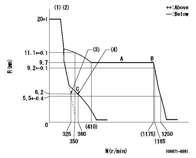
N:Pump speed
R:Rack position (mm)
(1)Target notch: K
(2)Tolerance for racks not indicated: +-0.05mm.
(3)Main spring setting
(4)Set idle sub-spring
----------
K=18
----------
----------
K=18
----------
Speed control lever angle

F:Full speed
I:Idle
(1)Stopper bolt setting
----------
----------
a=20deg+-5deg b=29deg+-5deg
----------
----------
a=20deg+-5deg b=29deg+-5deg
Stop lever angle
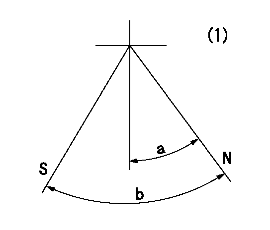
N:Pump normal
S:Stop the pump.
(1)No return spring
----------
----------
a=27deg+-5deg b=53deg+-5deg
----------
----------
a=27deg+-5deg b=53deg+-5deg
Timing setting

(1)Pump vertical direction
(2)Coupling's key groove position at No 1 cylinder's beginning of injection
(3)-
(4)-
----------
----------
a=(0deg)
----------
----------
a=(0deg)
Information:
Table 1
Required Tools
Tool Part Number Part Description Qty
A 380-5200 Tool Kit 1
B 366-7782 Attenuator 1 Testing Procedure
Perform a "Manual Diesel Particulate Filter Regeneration" using the electronic service tool. If the "Manual Diesel Particulate Filter Regeneration" procedure follows the removal of excess oil from the exhaust system, proceed to Step 2.
Follow the procedure that is detailed by Step 1.b through to Step 1.m to clean oil from the exhaust system.
Remove excess oil from all pipes with a clean cloth.
Remove the DPF from the bracket for the clean emission module. Refer to Disassembly and Assembly, "Diesel Particulate Filter - Remove" for the correct procedure.
Use a suitable supporting device, position the DPF in a vertical position. Ensure that the inlet side of the DPF faces in a DOWNWARDS position.
Let the DPF drain overnight. The oil will collect inside the inlet face of the DPF. Position a suitable container under the inlet face of the DPF. Incline the inlet face of the DPF to drain the oil into the container.
If amount drained from DPF equals less than 1 L (0.26 US gal), proceed to Step 1.g. If amount is greater than 1 L (0.26 US gal), then the DPF should be replaced.
Remove excess oil from the inlet and outlet of the DPF with a clean cloth.
Install the DPF from the bracket for the clean emission module. Refer to Disassembly and Assembly, "Diesel Particulate Filter - Install" for the correct procedure.
Start the engine. Operate the engine a 100 percent throttle for a MINIMUM of 20 minutes. Do not operate the application under load at this time period.
After 20 minutes, use the electronic service tool to perform the "DPF Desulphation Procedure". The "DPF Desulphation Procedure" will last 60 minutes.
Once the "DPF Desulphation Procedure" has been completed, observe the soot load. If the soot load is at a value less than 80 percent, then the application can be returned to service.
Check the application for any signs of visible black smoke coming from the exhaust stack after the cleaning procedure has been completed. This could indicate a cracked DPF that will need to be replaced.Note: Black soot residue on the surface of the inside of the exhaust stack does not necessarily indicate a cracked DPF therefore should not be used in determining a problem with the DPF.
If white smoke does not dissipate, contact the Technical Communicator at a Caterpillar dealer. For further assistance, the Technical Communicator can confer with the Dealer Solutions Network.
After the manual DPF regeneration is complete, operate the engine at 1800 rpm for a MINIMUM of 20 minutes to stabilize the DPF temperatures.Note: The engine must maintain a steady speed for the entire duration of the test.
Hot engine components can cause injury from burns. Before performing maintenance on the engine, allow the engine and the components to cool.
Illustration 1 g02597531
Typical example (1) DPF Outlet Cap (2) Filter Paper (3) Hose Assembly (4) Air Pump
Illustration