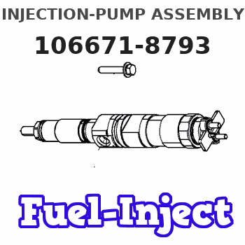
Information injection-pump assembly
BOSCH
9 400 610 893
9400610893
ZEXEL
106671-8793
1066718793

Rating:
Service parts 106671-8793 INJECTION-PUMP ASSEMBLY:
1.
_
7.
COUPLING PLATE
8.
_
9.
_
11.
Nozzle and Holder
23600-1970B
12.
Open Pre:MPa(Kqf/cm2)
21.6{220}
15.
NOZZLE SET
Include in #1:
106671-8793
as INJECTION-PUMP ASSEMBLY
Cross reference number
BOSCH
9 400 610 893
9400610893
ZEXEL
106671-8793
1066718793
Zexel num
Bosch num
Firm num
Name
Calibration Data:
Adjustment conditions
Test oil
1404 Test oil ISO4113 or {SAEJ967d}
1404 Test oil ISO4113 or {SAEJ967d}
Test oil temperature
degC
40
40
45
Nozzle and nozzle holder
105780-8140
Bosch type code
EF8511/9A
Nozzle
105780-0000
Bosch type code
DN12SD12T
Nozzle holder
105780-2080
Bosch type code
EF8511/9
Opening pressure
MPa
17.2
Opening pressure
kgf/cm2
175
Injection pipe
Outer diameter - inner diameter - length (mm) mm 8-3-600
Outer diameter - inner diameter - length (mm) mm 8-3-600
Overflow valve
134424-0920
Overflow valve opening pressure
kPa
162
147
177
Overflow valve opening pressure
kgf/cm2
1.65
1.5
1.8
Tester oil delivery pressure
kPa
157
157
157
Tester oil delivery pressure
kgf/cm2
1.6
1.6
1.6
Direction of rotation (viewed from drive side)
Left L
Left L
Injection timing adjustment
Direction of rotation (viewed from drive side)
Left L
Left L
Injection order
1-4-2-6-
3-5
Pre-stroke
mm
3.9
3.84
3.9
Beginning of injection position
Drive side NO.1
Drive side NO.1
Difference between angles 1
Cal 1-4 deg. 60 59.75 60.25
Cal 1-4 deg. 60 59.75 60.25
Difference between angles 2
Cyl.1-2 deg. 120 119.75 120.25
Cyl.1-2 deg. 120 119.75 120.25
Difference between angles 3
Cal 1-6 deg. 180 179.75 180.25
Cal 1-6 deg. 180 179.75 180.25
Difference between angles 4
Cal 1-3 deg. 240 239.75 240.25
Cal 1-3 deg. 240 239.75 240.25
Difference between angles 5
Cal 1-5 deg. 300 299.75 300.25
Cal 1-5 deg. 300 299.75 300.25
Injection quantity adjustment
Adjusting point
A
Rack position
11.4
Pump speed
r/min
1000
1000
1000
Average injection quantity
mm3/st.
204
202
206
Max. variation between cylinders
%
0
-2
2
Basic
*
Fixing the lever
*
Boost pressure
kPa
62
62
Boost pressure
mmHg
465
465
Injection quantity adjustment_02
Adjusting point
C
Rack position
5.2+-0.5
Pump speed
r/min
550
550
550
Average injection quantity
mm3/st.
12
9
15
Max. variation between cylinders
%
0
-15
15
Fixing the rack
*
Boost pressure
kPa
0
0
0
Boost pressure
mmHg
0
0
0
Injection quantity adjustment_03
Adjusting point
D
Rack position
-
Pump speed
r/min
100
100
100
Average injection quantity
mm3/st.
165
165
175
Fixing the lever
*
Boost pressure
kPa
0
0
0
Boost pressure
mmHg
0
0
0
Rack limit
*
Boost compensator adjustment
Pump speed
r/min
600
600
600
Rack position
R1-1.6
Boost pressure
kPa
20.7
18
23.4
Boost pressure
mmHg
155
135
175
Boost compensator adjustment_02
Pump speed
r/min
600
600
600
Rack position
R1(11.4)
Boost pressure
kPa
50
44.7
55.3
Boost pressure
mmHg
375
335
415
Timer adjustment
Pump speed
r/min
750--
Advance angle
deg.
0
0
0
Load
3/4
Remarks
Start
Start
Timer adjustment_02
Pump speed
r/min
700
Advance angle
deg.
0.3
Load
3/4
Timer adjustment_03
Pump speed
r/min
-
Advance angle
deg.
0
0
0
Load
4/4
Remarks
Measure speed (beginning of operation).
Measure speed (beginning of operation).
Timer adjustment_04
Pump speed
r/min
1000
Advance angle
deg.
3
2.7
3.3
Load
4/4
Remarks
Finish
Finish
Test data Ex:
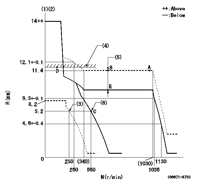
Governor adjustment

N:Pump speed
R:Rack position (mm)
(1)Target notch: K
(2)Tolerance for racks not indicated: +-0.05mm.
(3)Set idle sub-spring
(4)RACK LIMIT
(5)Boost compensator stroke: BCL
(6)Main spring setting
----------
K=14 BCL=1.6+-0.1mm
----------
----------
K=14 BCL=1.6+-0.1mm
----------
Speed control lever angle

F:Full speed
I:Idle
(1)Stopper bolt setting
----------
----------
a=7deg+-5deg b=17deg+-5deg
----------
----------
a=7deg+-5deg b=17deg+-5deg
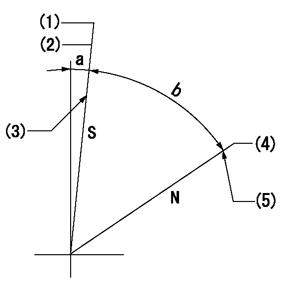
Stop lever angle

N:Pump normal
S:Stop the pump.
(1)Pump speed aa and rack position bb (to be sealed at delivery)
(2)At delivery
(3)Stopper bolt setting
(4)Rack position corresponding to cc (seal at delivery)
(5)Stopper bolt setting
----------
aa=0r/min bb=2.5-0.5mm cc=19.5mm
----------
a=5deg+-5deg b=55deg+-5deg
----------
aa=0r/min bb=2.5-0.5mm cc=19.5mm
----------
a=5deg+-5deg b=55deg+-5deg
Timing setting

(1)Pump vertical direction
(2)Coupling's key groove position at No 1 cylinder's beginning of injection
(3)-
(4)-
----------
----------
a=(0deg)
----------
----------
a=(0deg)
Information:
Do not use the same vacuum sampling pump for extracting oil samples that is used for extracting coolant samples.A small residue of either type sample may remain in the pump and may cause a false positive analysis for the sample being taken.Always use a separate pump for oil sampling and a separate pump for coolant sampling.Failure to do so may cause a false analysis which could lead to customer and dealer concerns.
Oil Sampling Interval
Take the oil samples as close as possible to the standard intervals. In order to receive the full value from S O S oil analysis, establish a consistent trend of data. In order to establish a pertinent history of data, perform consistent oil samplings that are evenly spaced.Recommended interval for engine oil samples is given in Table 2. A 250 hour sampling interval can provide a timely indication of oil contamination and oil degradation.Measure and record engine oil consumption in order to allow accurate oil analysis. Oil additions during the sampling interval dilute wear metals and other contaminants.
Table 2
S O S Oil Sampling Interval for Engine crankcase
Recommended Interval (1)(2) Oil Type
Every 250 Service Hours Cat DEO
Cat DEO-ULS
(1) Severe applications may require a more frequent oil sampling interval.
(2) Under certain conditions, the Cat dealer or the Operation and Maintenance Manual may allow a longer interval between oil samplings.Note: Refer to the Operation and Maintenance Manual for your engine for recommended oil drain intervals.Consult your Cat dealer for complete information and assistance in order to establish an S O S Services program for your engine.More Frequent S O S Sampling Improves Life Cycle Management
Traditionally, the suggested S O S sampling intervals for diesel engines have been at 250 hours. However in severe applications, more frequent oil sampling is recommended. Severe service for lubricated compartments occurs at high loads, in high temperatures, and in dusty conditions. If any of these conditions or other severe service indicators exist, sample the engine oil at 125 hour intervals. These additional samples will increase the chance of detecting a potential failure.Determining Optimum Oil Change Intervals
Sampling the engine oil at every 125 hours provides information for oil condition and for oil performance. This information is used to determine the optimum usable life of a particular oil. Also, more points of data will allow closer monitoring of component wear rates. Close monitoring also allows you to obtain the maximum use of the oil. For detailed information on optimizing oil change intervals, consult your Cat dealer.This Special Publication does not address recommended oil drain intervals. Refer to your engine Operation and Maintenance Manual, and consult your Cat dealer for additional guidance, including but not limited to guidance on establishing optimized and/or acceptable oil drain intervals.Note: The use of Cat S O S Services oil analysis helps environmental sustainability as the best way to optimize oil life. S O S Services will help engines reach expected life. Consult your Cat dealer regarding the testing required to establish a safe, optimized oil drain interval.Standard oil drain intervals as published
