Information injection-pump assembly
BOSCH
F 019 Z10 415
f019z10415
ZEXEL
106671-8740
1066718740
HINO
220204470A
220204470a
Rating:
Service parts 106671-8740 INJECTION-PUMP ASSEMBLY:
1.
_
7.
COUPLING PLATE
8.
_
9.
_
11.
Nozzle and Holder
236002191B
12.
Open Pre:MPa(Kqf/cm2)
21.6(220)
15.
NOZZLE SET
Include in #1:
106671-8740
as INJECTION-PUMP ASSEMBLY
Cross reference number
BOSCH
F 019 Z10 415
f019z10415
ZEXEL
106671-8740
1066718740
HINO
220204470A
220204470a
Zexel num
Bosch num
Firm num
Name
Calibration Data:
Adjustment conditions
Test oil
1404 Test oil ISO4113 or {SAEJ967d}
1404 Test oil ISO4113 or {SAEJ967d}
Test oil temperature
degC
40
40
45
Nozzle and nozzle holder
105780-8140
Bosch type code
EF8511/9A
Nozzle
105780-0000
Bosch type code
DN12SD12T
Nozzle holder
105780-2080
Bosch type code
EF8511/9
Opening pressure
MPa
17.2
Opening pressure
kgf/cm2
175
Injection pipe
Outer diameter - inner diameter - length (mm) mm 8-3-600
Outer diameter - inner diameter - length (mm) mm 8-3-600
Overflow valve (drive side)
134424-2020
Overflow valve opening pressure (drive side)
kPa
162
147
177
Overflow valve opening pressure (drive side)
kgf/cm2
1.65
1.5
1.8
Overflow valve (governor side)
134424-2120
Overflow valve opening pressure (governor side)
kPa
162
147
177
Overflow valve opening pressure (governor side)
kgf/cm2
1.65
1.5
1.8
Tester oil delivery pressure
kPa
157
157
157
Tester oil delivery pressure
kgf/cm2
1.6
1.6
1.6
Direction of rotation (viewed from drive side)
Right R
Right R
Injection timing adjustment
Direction of rotation (viewed from drive side)
Right R
Right R
Injection order
1-4-2-6-
3-5
Pre-stroke
mm
4.1
4.04
4.1
Beginning of injection position
Drive side NO.1
Drive side NO.1
Difference between angles 1
Cal 1-4 deg. 60 59.75 60.25
Cal 1-4 deg. 60 59.75 60.25
Difference between angles 2
Cyl.1-2 deg. 120 119.75 120.25
Cyl.1-2 deg. 120 119.75 120.25
Difference between angles 3
Cal 1-6 deg. 180 179.75 180.25
Cal 1-6 deg. 180 179.75 180.25
Difference between angles 4
Cal 1-3 deg. 240 239.75 240.25
Cal 1-3 deg. 240 239.75 240.25
Difference between angles 5
Cal 1-5 deg. 300 299.75 300.25
Cal 1-5 deg. 300 299.75 300.25
Injection quantity adjustment
Adjusting point
A
Rack position
10.7
Pump speed
r/min
1160
1160
1160
Average injection quantity
mm3/st.
212
208
216
Max. variation between cylinders
%
0
-2
2
Basic
*
Fixing the lever
*
Boost pressure
kPa
112
112
Boost pressure
mmHg
840
840
Injection quantity adjustment_02
Adjusting point
B
Rack position
4.5+-0.5
Pump speed
r/min
265
265
265
Average injection quantity
mm3/st.
11.5
8.5
14.5
Max. variation between cylinders
%
0
-15
15
Fixing the rack
*
Boost pressure
kPa
0
0
0
Boost pressure
mmHg
0
0
0
Injection quantity adjustment_03
Adjusting point
C
Rack position
-
Pump speed
r/min
100
100
100
Average injection quantity
mm3/st.
220
220
240
Fixing the lever
*
Boost pressure
kPa
0
0
0
Boost pressure
mmHg
0
0
0
Remarks
Excess lever at excess.
Excess lever at excess.
Boost compensator adjustment
Pump speed
r/min
500
500
500
Rack position
7.7
Boost pressure
kPa
10.7
8
13.4
Boost pressure
mmHg
80
60
100
Boost compensator adjustment_02
Pump speed
r/min
500
500
500
Rack position
(10.7)
Boost pressure
kPa
98.6
98.6
98.6
Boost pressure
mmHg
740
740
740
Timer adjustment
Pump speed
r/min
(N1+50)-
-
Advance angle
deg.
0
0
0
Remarks
Start
Start
Timer adjustment_02
Pump speed
r/min
N1
Advance angle
deg.
0.3
Remarks
Measure the actual speed.
Measure the actual speed.
Timer adjustment_03
Pump speed
r/min
-
Advance angle
deg.
1
0.7
1.3
Remarks
Measure the actual speed, stop
Measure the actual speed, stop
Test data Ex:
Governor adjustment
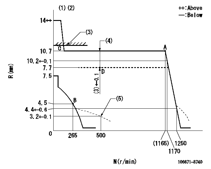
N:Pump speed
R:Rack position (mm)
(1)Target notch: K
(2)Tolerance for racks not indicated: +-0.05mm.
(3)Excessive fuel lever setting (boost pressure 0)
(4)Boost compensator stroke (at N = N1)
(5)Damper spring setting
----------
K=11 N1=500r/min
----------
----------
K=11 N1=500r/min
----------
Speed control lever angle
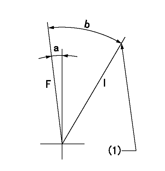
F:Full speed
I:Idle
(1)Stopper bolt setting
----------
----------
a=7deg+-5deg b=31deg+-5deg
----------
----------
a=7deg+-5deg b=31deg+-5deg
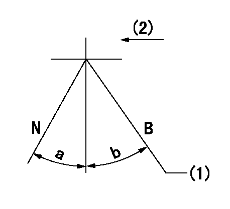
Stop lever angle

N:Pump normal
S:Stop the pump.
(1)Rack position aa or less, pump speed bb
----------
aa=4mm bb=0r/min
----------
a=27deg+-5deg b=53deg+-5deg
----------
aa=4mm bb=0r/min
----------
a=27deg+-5deg b=53deg+-5deg
0000001101
N:Normal
B:When boosted
(1)When setting point C (at 0 boost pressure)
(2)Drive side
----------
----------
a=(15deg) b=(15deg)
----------
----------
a=(15deg) b=(15deg)
Timing setting

(1)Pump vertical direction
(2)Coupling's key groove position at No 1 cylinder's beginning of injection
(3)-
(4)-
----------
----------
a=(50deg)
----------
----------
a=(50deg)
Information:
Introduction
The problem that is identified now has a known permanent solution. Components to perform repairs are limited at this time. Review the solution below for further details. Problem
Caterpillar is aware of recent failures of the 8N-1721 Connecting Rod and the 8N-1984 Connecting Rod on certain diesel and gas applications of 3300 engines. Primary failure mode is a ventilated cylinder block due to the connecting rod crank end failure. All failures have occurred before 500 hours in service. Root cause has been identified and the team is working to resolve the issue. Solution
A "Quality Hold" is active for all new assemblies that utilize the 8N-1984 Connecting Rod and the 8N-1721 Connecting Rod manufactured between 01April 2011 and 31December 2012. The "Quality Hold" is applicable to all Morton service stock also.Cat ® Reman has identified a list of part numbers for Service kits, Piston Packs, and Rod Assembly boxes that may contain defective factory connecting rod assemblies. Dealers are advised not to use any factory new connecting rod assemblies that are found in the kits or assemblies prior to examination. Refer to Table 1.
Table 1
Service kit, Piston Pack, and Rod Assembly Part Numbers That May Contain the Defective New Connecting Rod Assemblies
8N-1721 20R-1439 20R-1474
0R-1696 20R-1428 20R-1660
0R-1697 0R-9206 20R-1442
0R-3043 20R-1462 20R-1482
10R-3637 20R-1455 20R-1483
10R-9259 20R-1477 20R-1451
0R-1694 20R-1472 20R-1450
0R-4284 20R-1448 20R-1445
0R-1695 20R-1446 20R-1443
0R-4635 20R-1468 20R-1426
0R-4488 20R-1466 20R-1423
0R-4506 20R-1441 0R-2078
0R-3044 20R-1437 0R-3258
0R-2080 20R-1435 20R-1665
0R-3259 20R-1434 20R-1663
0R-3612 20R-1429 20R-1675
0R-3610 20R-1424 0R-3661
10R-6152 0R-2557 0R-1692
20R-1673 0R-2079 0R-1693
20R-1664 20R-1341 0R-3660
0R-4949 0R-2555 0R-3662
0R-9205 0R-3613 20R-1127
0R-2556 0R-4956 8N-1984
0R-3706 0R-2554
10R-1851 0R-4948
10R-1636 10R-0889
10R-1840 0R-3611
0R-2077 10R-7253
20R-1454 0R-7444 When an engine failure occurs due to the connecting rod assembly, dealers are asked to contact the Dealer Solution Network (DSN) Tier 2 core engine service engineer at Mossville Engine Center (MEC) to expedite support to the customer.To support field repairs and rebuilds, dealers are advised to inspect the manufacture date on any 3304, G3304, 3306, or G3306 engine with the 8N-1984 Connecting Rod , the 8N-1721 Connecting Rod , the 0R-0914 Connecting Rod , and the 0R-0915 Connecting Rod , used to perform repairs. If the manufacture date is within the suspect date range, do not use the part. Parts stocking service letters will be released soon to address suspect material in dealer inventories. Markings on the Suspect 8N-1984 Connecting Rod and the 8N-1721 Connecting Rod
Illustration 1 g03342875
(1