Information injection-pump assembly
ZEXEL
106671-8650
1066718650

Rating:
Service parts 106671-8650 INJECTION-PUMP ASSEMBLY:
1.
_
7.
COUPLING PLATE
8.
_
9.
_
11.
Nozzle and Holder
23600-1611B
12.
Open Pre:MPa(Kqf/cm2)
21.6{220}
15.
NOZZLE SET
Include in #1:
106671-8650
as INJECTION-PUMP ASSEMBLY
Cross reference number
ZEXEL
106671-8650
1066718650
Zexel num
Bosch num
Firm num
Name
106671-8650
INJECTION-PUMP ASSEMBLY
14CA PE6P,6PD PE
14CA PE6P,6PD PE
Calibration Data:
Adjustment conditions
Test oil
1404 Test oil ISO4113 or {SAEJ967d}
1404 Test oil ISO4113 or {SAEJ967d}
Test oil temperature
degC
40
40
45
Nozzle and nozzle holder
105780-8140
Bosch type code
EF8511/9A
Nozzle
105780-0000
Bosch type code
DN12SD12T
Nozzle holder
105780-2080
Bosch type code
EF8511/9
Opening pressure
MPa
17.2
Opening pressure
kgf/cm2
175
Injection pipe
Outer diameter - inner diameter - length (mm) mm 8-3-600
Outer diameter - inner diameter - length (mm) mm 8-3-600
Overflow valve
134424-0920
Overflow valve opening pressure
kPa
162
147
177
Overflow valve opening pressure
kgf/cm2
1.65
1.5
1.8
Tester oil delivery pressure
kPa
157
157
157
Tester oil delivery pressure
kgf/cm2
1.6
1.6
1.6
Direction of rotation (viewed from drive side)
Left L
Left L
Injection timing adjustment
Direction of rotation (viewed from drive side)
Left L
Left L
Injection order
1-4-2-6-
3-5
Pre-stroke
mm
3.3
3.2
3.3
Beginning of injection position
Drive side NO.1
Drive side NO.1
Difference between angles 1
Cal 1-4 deg. 60 59.5 60.5
Cal 1-4 deg. 60 59.5 60.5
Difference between angles 2
Cyl.1-2 deg. 120 119.5 120.5
Cyl.1-2 deg. 120 119.5 120.5
Difference between angles 3
Cal 1-6 deg. 180 179.5 180.5
Cal 1-6 deg. 180 179.5 180.5
Difference between angles 4
Cal 1-3 deg. 240 239.5 240.5
Cal 1-3 deg. 240 239.5 240.5
Difference between angles 5
Cal 1-5 deg. 300 299.5 300.5
Cal 1-5 deg. 300 299.5 300.5
Injection quantity adjustment
Adjusting point
A
Rack position
9.7
Pump speed
r/min
700
700
700
Average injection quantity
mm3/st.
138
135
141
Max. variation between cylinders
%
0
-4
4
Basic
*
Fixing the lever
*
Injection quantity adjustment_02
Adjusting point
C
Rack position
6.1+-0.5
Pump speed
r/min
360
360
360
Average injection quantity
mm3/st.
13.5
10.5
16.5
Max. variation between cylinders
%
0
-15
15
Fixing the rack
*
Timer adjustment
Pump speed
r/min
750--
Advance angle
deg.
0
0
0
Remarks
Start
Start
Timer adjustment_02
Pump speed
r/min
700
Advance angle
deg.
0.5
Timer adjustment_03
Pump speed
r/min
900
Advance angle
deg.
1.4
0.9
1.9
Timer adjustment_04
Pump speed
r/min
1100
Advance angle
deg.
3.5
3
4
Timer adjustment_05
Pump speed
r/min
-
Advance angle
deg.
4
4
4
Remarks
Measure the actual speed, stop
Measure the actual speed, stop
Test data Ex:
Governor adjustment
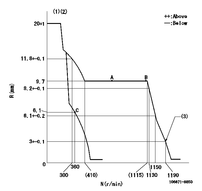
N:Pump speed
R:Rack position (mm)
(1)Target notch: K
(2)Tolerance for racks not indicated: +-0.05mm.
(3)Set idle sub-spring
----------
K=12
----------
----------
K=12
----------
Speed control lever angle

F:Full speed
I:Idle
(1)Stopper bolt setting
----------
----------
a=18deg+-5deg b=32deg+-5deg
----------
----------
a=18deg+-5deg b=32deg+-5deg
Stop lever angle

N:Pump normal
S:Stop the pump.
----------
----------
a=27deg+-5deg b=53deg+-5deg
----------
----------
a=27deg+-5deg b=53deg+-5deg
Timing setting

(1)Pump vertical direction
(2)Coupling's key groove position at No 1 cylinder's beginning of injection
(3)-
(4)-
----------
----------
a=(0deg)
----------
----------
a=(0deg)
Information:
Table 3
Injector Resistance Measurement
Step Instruction Completed
(Yes/No) Results
Comments Units
1 Turn the keyswitch to the OFF position. Allow 2 minutes to elapse before proceeding.
2 Disconnect the DEF injector from the applicable harness.
3 Inspect the connector for damage or debris (if damaged take photo)
4 Measure the temperature of the injector (aluminum body) C
5 Connect two 398-4987 connectors to the DEF injector. The connectors must be used to prevent damage to the DEF injector connector.
6 Measure the resistance of the DEF injector. Ohms
Table 4
Dosing Accuracy Test
Step Instruction Completed
(Yes/No) Results
Comments Units
1 Follow the Testing and Adjusting, Aftertreatment SCR System Dosing - Test.
2 Remove the injector from the DPF outlet.
3 Take a photograph of the DEF injector mount on the DPF outlet and the tip of the DEF injector.
4 Install the injector on the beaker.
5 Run the DEF System Dosing Accuracy test through Cat ET.
6 Use the breaker to measure the amount of fluid from the dosing test. ml
7 Repeat the test to verify consistency. ml
8 Install the injector back onto the DPF outlet.
Illustration 2 g06068068
DEF Injector Resistance Measurement
Illustration 3 g06067706
Injector Mount on DPF (Outlet Sample Picture)
Illustration 4 g06067753
DEF Injector Tip (Sample Picture)
When troubleshooting requests the DEF quality check, DEF injector resistance measurement or Dosing Accuracy Test, please document results in the Tables shown above.
After completing troubleshooting and performing the Aftertreatment System Functional Test, download a new Product Status Report with all ECM's.
Table 5
Injector Failure Report
Step Instruction Completed
(Yes/No) Results
Comments Units
1 Download "Product Status Report" (PSR) from the engine ECM and send to the email address in the instructions.
2 Download "Warranty Report" (WR) from the engine ECM and send to the email address in the instructions.
3 Take a picture of the injector part number / serial number.
4 Follow the correct TSG based on Table 1 and complete tables 2 through 4 when they apply.
5 Perform an "Aftertreatment System Functional Test".
6 Download "Product Status Report" (PSR) from the engine ECM and send to the email address in the instructions.
7 Submit "TIB Check List", "Product Status Reports", DEF injector deposits photographs, CEM deposit photographs, and DEF injector part number and serial number photograph to the email address in the instructions.
Fill out the Injector Failure Report and send all information including product status reports, warranty reports, DEF injector and mount photos, DEF injector part number and serial number and test results to the email address provided above.
Have questions with 106671-8650?
Group cross 106671-8650 ZEXEL
Hino
Hino
Hino
106671-8650
INJECTION-PUMP ASSEMBLY