Information injection-pump assembly
ZEXEL
106671-8560
1066718560

Rating:
Service parts 106671-8560 INJECTION-PUMP ASSEMBLY:
1.
_
7.
COUPLING PLATE
8.
_
9.
_
11.
Nozzle and Holder
23600-1860D
12.
Open Pre:MPa(Kqf/cm2)
21.6{220}
15.
NOZZLE SET
Include in #1:
106671-8560
as INJECTION-PUMP ASSEMBLY
Cross reference number
ZEXEL
106671-8560
1066718560
Zexel num
Bosch num
Firm num
Name
106671-8560
INJECTION-PUMP ASSEMBLY
14CA PE6P,6PD PE
14CA PE6P,6PD PE
Calibration Data:
Adjustment conditions
Test oil
1404 Test oil ISO4113 or {SAEJ967d}
1404 Test oil ISO4113 or {SAEJ967d}
Test oil temperature
degC
40
40
45
Nozzle and nozzle holder
105780-8140
Bosch type code
EF8511/9A
Nozzle
105780-0000
Bosch type code
DN12SD12T
Nozzle holder
105780-2080
Bosch type code
EF8511/9
Opening pressure
MPa
17.2
Opening pressure
kgf/cm2
175
Injection pipe
Outer diameter - inner diameter - length (mm) mm 8-3-600
Outer diameter - inner diameter - length (mm) mm 8-3-600
Overflow valve
134424-0920
Overflow valve opening pressure
kPa
162
147
177
Overflow valve opening pressure
kgf/cm2
1.65
1.5
1.8
Tester oil delivery pressure
kPa
157
157
157
Tester oil delivery pressure
kgf/cm2
1.6
1.6
1.6
Direction of rotation (viewed from drive side)
Left L
Left L
Injection timing adjustment
Direction of rotation (viewed from drive side)
Left L
Left L
Injection order
1-4-2-6-
3-5
Pre-stroke
mm
3.3
3.2
3.3
Beginning of injection position
Drive side NO.1
Drive side NO.1
Difference between angles 1
Cal 1-4 deg. 60 59.5 60.5
Cal 1-4 deg. 60 59.5 60.5
Difference between angles 2
Cyl.1-2 deg. 120 119.5 120.5
Cyl.1-2 deg. 120 119.5 120.5
Difference between angles 3
Cal 1-6 deg. 180 179.5 180.5
Cal 1-6 deg. 180 179.5 180.5
Difference between angles 4
Cal 1-3 deg. 240 239.5 240.5
Cal 1-3 deg. 240 239.5 240.5
Difference between angles 5
Cal 1-5 deg. 300 299.5 300.5
Cal 1-5 deg. 300 299.5 300.5
Injection quantity adjustment
Adjusting point
A
Rack position
9.6
Pump speed
r/min
900
900
900
Average injection quantity
mm3/st.
128.1
126.1
130.1
Max. variation between cylinders
%
0
-4
4
Basic
*
Fixing the lever
*
Injection quantity adjustment_02
Adjusting point
C
Rack position
4.8+-0.5
Pump speed
r/min
400
400
400
Average injection quantity
mm3/st.
11.8
8.8
14.8
Max. variation between cylinders
%
0
-15
15
Fixing the rack
*
Timer adjustment
Pump speed
r/min
900++
Advance angle
deg.
0
0
0
Remarks
Do not advance until starting N = 900.
Do not advance until starting N = 900.
Timer adjustment_02
Pump speed
r/min
-
Advance angle
deg.
4.5
4.5
4.5
Remarks
Measure the actual speed, stop
Measure the actual speed, stop
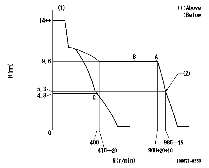
Test data Ex:
Governor adjustment

N:Pump speed
R:Rack position (mm)
(1)Target notch: K
(2)Idle sub spring setting: L1.
----------
K=10 L1=5.3-0.5mm
----------
----------
K=10 L1=5.3-0.5mm
----------
Speed control lever angle

F:Full speed
I:Idle
(1)Stopper bolt setting
----------
----------
a=1deg+-5deg b=17deg+-5deg
----------
----------
a=1deg+-5deg b=17deg+-5deg
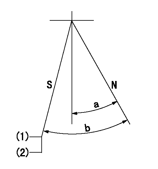
Stop lever angle

N:Pump normal
S:Stop the pump.
(1)At delivery
(2)Rack position aa or less, pump speed bb
----------
aa=4.3mm bb=0r/min
----------
a=38deg+-5deg b=53deg+-5deg
----------
aa=4.3mm bb=0r/min
----------
a=38deg+-5deg b=53deg+-5deg
Timing setting

(1)Pump vertical direction
(2)Coupling's key groove position at No 1 cylinder's beginning of injection
(3)-
(4)-
----------
----------
a=(0deg)
----------
----------
a=(0deg)
Information:
Introduction
Do not perform any procedure in this Special Instruction until you have read this information and you understand this information.Required Parts
Table 1
Required Parts
Item Qty New Part Number Part Name
1 2 137-8101 O-Ring Seal
2 2 286-5030 Elbow
3 1 289-3891 Clip
4 1 294-6118 Pressure Sensor
5 1 356-0920 Bracket
6 2 3J-7352 Connector
7 2 6V-5048 O-Ring Seal
8 2 8T-0267 Bolt
9 2 9X-8267 Washer
10 108-9656 Cable Straps
11 2 5P-1717 Hose Clamp
12 1 356-6802 Sensor Harness As
13 1 289-3891 Clip
14 2 5P-3860 Hose Clamp Procedure
Illustration 1 g02082554
Example of a vertical filter group (1) Connection for the pressure sensor group (2) New bypass wiring harness (3) Connection for the mounted sensor group (4) OEM wiring harness connection (5) OEM wiring harness (6) Wire for the probe of the outlet temperature is secured to the new P1 tube. (7) Support bracket for the new P1 tube (8) New P1 tube (9) The wire for the probe for the inlet temperature is secured to new P1 tube. (10) New P2 tubeNote: Avoid placing
Have questions with 106671-8560?
Group cross 106671-8560 ZEXEL
106671-8560
INJECTION-PUMP ASSEMBLY
