Information injection-pump assembly
BOSCH
F 01G 09U 07U
f01g09u07u
ZEXEL
106671-8553
1066718553
HINO
220007523A
220007523a
Rating:
Service parts 106671-8553 INJECTION-PUMP ASSEMBLY:
1.
_
7.
COUPLING PLATE
8.
_
9.
_
11.
Nozzle and Holder
23600-2470C
12.
Open Pre:MPa(Kqf/cm2)
14.7{150}/21.6{220}
14.
NOZZLE
Include in #1:
106671-8553
as INJECTION-PUMP ASSEMBLY
Cross reference number
BOSCH
F 01G 09U 07U
f01g09u07u
ZEXEL
106671-8553
1066718553
HINO
220007523A
220007523a
Zexel num
Bosch num
Firm num
Name
Calibration Data:
Adjustment conditions
Test oil
1404 Test oil ISO4113 or {SAEJ967d}
1404 Test oil ISO4113 or {SAEJ967d}
Test oil temperature
degC
40
40
45
Nozzle and nozzle holder
105780-8140
Bosch type code
EF8511/9A
Nozzle
105780-0000
Bosch type code
DN12SD12T
Nozzle holder
105780-2080
Bosch type code
EF8511/9
Opening pressure
MPa
17.2
Opening pressure
kgf/cm2
175
Injection pipe
Outer diameter - inner diameter - length (mm) mm 8-3-600
Outer diameter - inner diameter - length (mm) mm 8-3-600
Overflow valve
134424-1420
Overflow valve opening pressure
kPa
162
147
177
Overflow valve opening pressure
kgf/cm2
1.65
1.5
1.8
Tester oil delivery pressure
kPa
157
157
157
Tester oil delivery pressure
kgf/cm2
1.6
1.6
1.6
Direction of rotation (viewed from drive side)
Left L
Left L
Injection timing adjustment
Direction of rotation (viewed from drive side)
Left L
Left L
Injection order
1-4-2-6-
3-5
Pre-stroke
mm
4.6
4.54
4.6
Beginning of injection position
Drive side NO.1
Drive side NO.1
Difference between angles 1
Cal 1-4 deg. 60 59.75 60.25
Cal 1-4 deg. 60 59.75 60.25
Difference between angles 2
Cyl.1-2 deg. 120 119.75 120.25
Cyl.1-2 deg. 120 119.75 120.25
Difference between angles 3
Cal 1-6 deg. 180 179.75 180.25
Cal 1-6 deg. 180 179.75 180.25
Difference between angles 4
Cal 1-3 deg. 240 239.75 240.25
Cal 1-3 deg. 240 239.75 240.25
Difference between angles 5
Cal 1-5 deg. 300 299.75 300.25
Cal 1-5 deg. 300 299.75 300.25
Injection quantity adjustment
Adjusting point
A
Rack position
7.2
Pump speed
r/min
500
500
500
Average injection quantity
mm3/st.
141.4
138.4
144.4
Fixing the lever
*
Injection quantity adjustment_02
Adjusting point
B
Rack position
7.5
Pump speed
r/min
700
700
700
Average injection quantity
mm3/st.
149.7
147.7
151.7
Max. variation between cylinders
%
0
-2
2
Basic
*
Fixing the lever
*
Injection quantity adjustment_03
Adjusting point
C
Rack position
7.7
Pump speed
r/min
1075
1075
1075
Average injection quantity
mm3/st.
155.8
152.8
158.8
Fixing the lever
*
Injection quantity adjustment_04
Adjusting point
D
Rack position
3.7+-0.5
Pump speed
r/min
225
225
225
Average injection quantity
mm3/st.
8.8
5.8
11.8
Max. variation between cylinders
%
0
-15
15
Fixing the rack
*
Injection quantity adjustment_05
Adjusting point
F
Rack position
-
Pump speed
r/min
100
100
100
Average injection quantity
mm3/st.
160
160
180
Fixing the lever
*
Remarks
After startup boost setting
After startup boost setting
Timer adjustment
Pump speed
r/min
695--
Advance angle
deg.
0
0
0
Load
1/4
Remarks
Start
Start
Timer adjustment_02
Pump speed
r/min
645
Advance angle
deg.
0.3
Load
1/4
Timer adjustment_03
Pump speed
r/min
800
Advance angle
deg.
1
0.7
1.3
Load
4/4
Timer adjustment_04
Pump speed
r/min
860+50
Advance angle
deg.
1
0.7
1.3
Load
3/4
Timer adjustment_05
Pump speed
r/min
1075-50
Advance angle
deg.
5.5
5.2
5.8
Load
4/4
Remarks
Finish
Finish
Test data Ex:
Governor adjustment
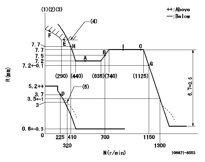
N:Pump speed
R:Rack position (mm)
(1)Lever ratio: RT
(2)Target shim dimension: TH
(3)Tolerance for racks not indicated: +-0.05mm.
(4)Excess fuel setting for starting: SXL (N = N1)
(5)Damper spring setting
----------
RT=0.8 TH=2.6mm SXL=8+-0.1mm N1=350r/min
----------
----------
RT=0.8 TH=2.6mm SXL=8+-0.1mm N1=350r/min
----------
Speed control lever angle

F:Full speed
----------
----------
a=15deg+-5deg
----------
----------
a=15deg+-5deg
0000000901
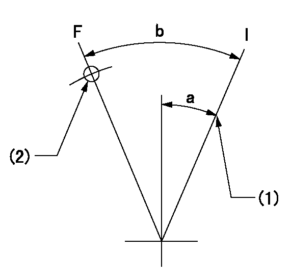
F:Full load
I:Idle
(1)Stopper bolt setting
(2)Use the hole at R = aa
----------
aa=45mm
----------
a=24deg+-5deg b=35deg+-3deg
----------
aa=45mm
----------
a=24deg+-5deg b=35deg+-3deg
Stop lever angle
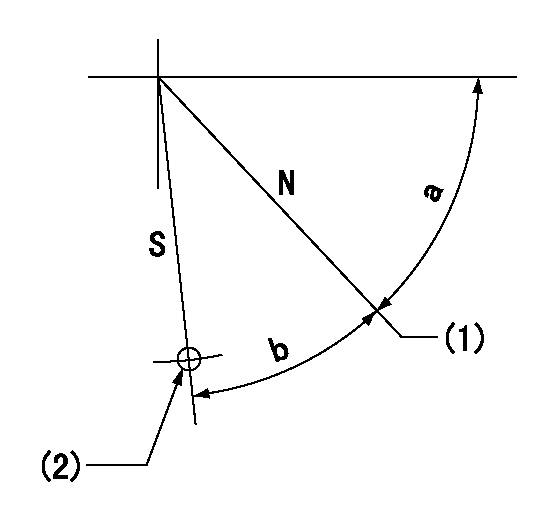
N:Pump normal
S:Stop the pump.
(1)Set stopper screw so that rack position = aa (after setting, apply red paint).
(2)Use the hole at R = bb
----------
aa=(13)+-1mm bb=36mm
----------
a=47deg+-5deg b=33.5deg+-5deg
----------
aa=(13)+-1mm bb=36mm
----------
a=47deg+-5deg b=33.5deg+-5deg
0000001501 GOVERNOR TORQUE CONTROL

Dr:Torque control stroke
(A): Without torque control spring capsule
1. Adjustment procedures
(1)Procedure is the same as that for the RFD (former type), except that the positive torque control stroke must be determined at the full lever setting.
2. Procedures for adjustment
(1)Remove the torque control spring capsule.
(2)Operate the pump at approximately N1. (End of idling spring operation < N1.)
(3)Tilt the lever to the full side.
(4)Set so that R = RF.
(5)Increase the speed by pushing in the screw (attached to the bracket on the rear of the tension lever) through the adjusting window.
(6)Adjust so that the torque control stroke Dr1 can be obtained.
(7)Align N2 and N3 with the torque control spring capsule.
3. Final confirmation
(1)After final confirmation, temporarily set the load lever to N = N1, R = idling position.
(2)From this condition, increase speed to N = N4.
(3)Confirm that positive torque control stroke is Dr2.
----------
N1=500r/min N2=(635)r/min N3=(740)r/min N4=850r/min RF=7.2mm Dr1=0.5mm Dr2=0+0.3mm
----------
----------
N1=500r/min N2=(635)r/min N3=(740)r/min N4=850r/min RF=7.2mm Dr1=0.5mm Dr2=0+0.3mm
----------
0000001601 RACK SENSOR

(VR) measurement voltage
(I) Part number of the control unit
(G) Apply red paint.
(H): End surface of the pump
1. Rack sensor adjustment (-0620)
(1)Fix the speed control lever at the full position
(2)Set the speed to N1 r/min.
(If the boost compensator is provided, apply boost pressure.)
(3)Adjust the bobbin (A) so that the rack sensor's output voltage is VR+-0.01.
(4)At that time, rack position must be Ra.
(5)Apply G at two places.
Connecting part between the joint (B) and the nut (F)
Connecting part between the joint (B) and the end surface of the pump (H)
----------
N1=900r/min Ra=7.7mm
----------
----------
N1=900r/min Ra=7.7mm
----------
Timing setting

(1)Pump vertical direction
(2)Coupling's key groove position at No 1 cylinder's beginning of injection
(3)-
(4)-
----------
----------
a=(3deg)
----------
----------
a=(3deg)
Information:
Introduction
Do not perform any procedure that is outlined in this Special Instruction until you have read and understand the information contained in this document.Required Parts
Table 1
Required Parts
Item Qty Part Number Part Name
1 1 360-9664 Tool Kit
2 1 399-7930 Cap Kit Testing Procedure
Use Caterpillar Electronic Technician (ET) to perform a "Manual Diesel Particulate Filter Regeneration".
Once the regeneration is complete, wait for the engine to drop to idle before shutting off the engine. The regeneration takes approximately 20 minutes.
Allow the system to cool down before handling.
While waiting for the exhaust to cool, perform the following actions.
Record the "Idle Speed Limit". Use Cat ET to change the "Idle RPM Limit" to 2100 rpm.
Use Cat ET to disable the automatic regeneration. A "Check Engine" light with active code 3714-31 will be present.
Remove the exhaust piping after the DPF. Install the 3 inch orifice plate for C13 and C15 engines. Install the 2 inch orifice plate for C7 and C9 engines. The 2 inch orifice plate is part of the 399-7930 Cap Kit .For a DPF with a dual outlet, use the solid cap that is provided and cap one of the outlets.For a dual DPF with one end cap, use a 313-3496 Plug to plug the drain hole, one 3L-7055 Pipe Connector , one 001-6449 Connector , and filter paper. Remove the delta P sensor from each DPF. Insert one 3L-7055 Pipe Connector , one 001-6449 Connector , and filter paper into each DPF. This action allows both diesel particulate filters to be tested at the same time.Note: The 313-3496 Plug , the 001-6449 Connector , and the 3L-7055 Pipe Connector is not included in the kit.
Start the engine. Run the engine at 2100 rpm for a minimum of 10 minutes to stabilize DPF temperatures.
Shut down the engine and install the filter holder in the drain port.Note: Do not wait more than 10 minutes after the engine has shut down to install the filter.
Run the engine at 2100 rpm for 20 minutes.
Shut down the engine and remove the filter holder. Use proper personal protective equipment to remove the filter holder.Note: Do not wait more than 10 minutes after the engine has shut down to remove the filter holder.
Warning: The filter holder will still be hot.
Wait for the filter holder to cool down before disassembly.
Carefully disassemble the filter holder to prevent contamination.
Tip the fitting over on a clean surface to remove the filter paper.
Handle the filter paper with clean hands. Only handle the filter paper by the edges.
Compare the stained area in the center of the filter paper to the color coded sheet that is provided.If the stained area of the filter paper is as dark or darker than colored circle 2, then the DPF may have to be replaced.If a DPF fails the test, then contact the DPF hotline to verify the failure and have a new DPF released.