Information injection-pump assembly
BOSCH
F 01G 09U 07T
f01g09u07t
ZEXEL
106671-8552
1066718552
Rating:
Cross reference number
BOSCH
F 01G 09U 07T
f01g09u07t
ZEXEL
106671-8552
1066718552
Zexel num
Bosch num
Firm num
Name
Calibration Data:
Adjustment conditions
Test oil
1404 Test oil ISO4113 or {SAEJ967d}
1404 Test oil ISO4113 or {SAEJ967d}
Test oil temperature
degC
40
40
45
Nozzle and nozzle holder
105780-8140
Bosch type code
EF8511/9A
Nozzle
105780-0000
Bosch type code
DN12SD12T
Nozzle holder
105780-2080
Bosch type code
EF8511/9
Opening pressure
MPa
17.2
Opening pressure
kgf/cm2
175
Injection pipe
Outer diameter - inner diameter - length (mm) mm 8-3-600
Outer diameter - inner diameter - length (mm) mm 8-3-600
Overflow valve
134424-1420
Overflow valve opening pressure
kPa
162
147
177
Overflow valve opening pressure
kgf/cm2
1.65
1.5
1.8
Tester oil delivery pressure
kPa
157
157
157
Tester oil delivery pressure
kgf/cm2
1.6
1.6
1.6
Direction of rotation (viewed from drive side)
Left L
Left L
Injection timing adjustment
Direction of rotation (viewed from drive side)
Left L
Left L
Injection order
1-4-2-6-
3-5
Pre-stroke
mm
4.6
4.54
4.6
Beginning of injection position
Drive side NO.1
Drive side NO.1
Difference between angles 1
Cal 1-4 deg. 60 59.75 60.25
Cal 1-4 deg. 60 59.75 60.25
Difference between angles 2
Cyl.1-2 deg. 120 119.75 120.25
Cyl.1-2 deg. 120 119.75 120.25
Difference between angles 3
Cal 1-6 deg. 180 179.75 180.25
Cal 1-6 deg. 180 179.75 180.25
Difference between angles 4
Cal 1-3 deg. 240 239.75 240.25
Cal 1-3 deg. 240 239.75 240.25
Difference between angles 5
Cal 1-5 deg. 300 299.75 300.25
Cal 1-5 deg. 300 299.75 300.25
Injection quantity adjustment
Adjusting point
A
Rack position
7.2
Pump speed
r/min
500
500
500
Average injection quantity
mm3/st.
141.4
138.4
144.4
Fixing the lever
*
Injection quantity adjustment_02
Adjusting point
B
Rack position
7.5
Pump speed
r/min
700
700
700
Average injection quantity
mm3/st.
149.7
147.7
151.7
Max. variation between cylinders
%
0
-2
2
Basic
*
Fixing the lever
*
Injection quantity adjustment_03
Adjusting point
C
Rack position
7.7
Pump speed
r/min
1075
1075
1075
Average injection quantity
mm3/st.
155.8
152.8
158.8
Fixing the lever
*
Injection quantity adjustment_04
Adjusting point
D
Rack position
3.7+-0.5
Pump speed
r/min
225
225
225
Average injection quantity
mm3/st.
8.8
5.8
11.8
Max. variation between cylinders
%
0
-15
15
Fixing the rack
*
Injection quantity adjustment_05
Adjusting point
F
Rack position
-
Pump speed
r/min
100
100
100
Average injection quantity
mm3/st.
160
160
180
Fixing the lever
*
Remarks
After startup boost setting
After startup boost setting
Timer adjustment
Pump speed
r/min
695--
Advance angle
deg.
0
0
0
Load
1/4
Remarks
Start
Start
Timer adjustment_02
Pump speed
r/min
645
Advance angle
deg.
0.3
Load
1/4
Timer adjustment_03
Pump speed
r/min
800
Advance angle
deg.
1
0.7
1.3
Load
4/4
Timer adjustment_04
Pump speed
r/min
860+50
Advance angle
deg.
1
0.7
1.3
Load
3/4
Timer adjustment_05
Pump speed
r/min
1075-50
Advance angle
deg.
5.5
5.2
5.8
Load
4/4
Remarks
Finish
Finish
Test data Ex:
Governor adjustment
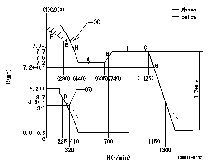
N:Pump speed
R:Rack position (mm)
(1)Lever ratio: RT
(2)Target shim dimension: TH
(3)Tolerance for racks not indicated: +-0.05mm.
(4)Excess fuel setting for starting: SXL (N = N1)
(5)Damper spring setting
----------
RT=0.8 TH=2.6mm SXL=8+-0.1mm N1=350r/min
----------
----------
RT=0.8 TH=2.6mm SXL=8+-0.1mm N1=350r/min
----------
Speed control lever angle

F:Full speed
----------
----------
a=15deg+-5deg
----------
----------
a=15deg+-5deg
0000000901
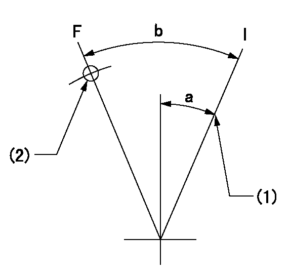
F:Full load
I:Idle
(1)Stopper bolt setting
(2)Use the hole at R = aa
----------
aa=45mm
----------
a=24deg+-5deg b=35deg+-3deg
----------
aa=45mm
----------
a=24deg+-5deg b=35deg+-3deg
Stop lever angle
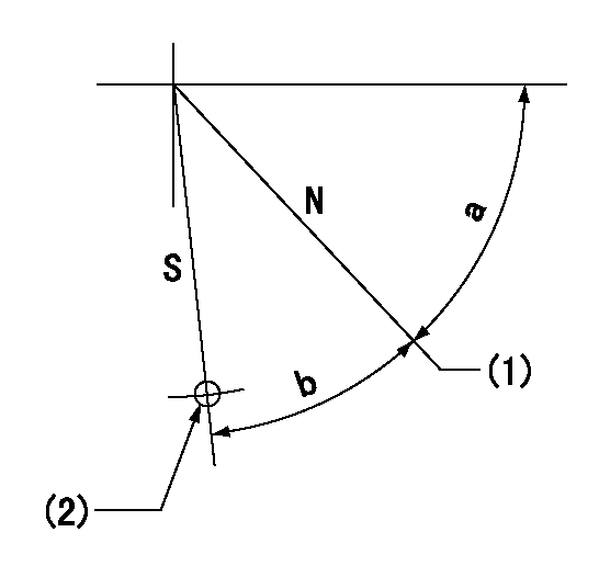
N:Pump normal
S:Stop the pump.
(1)Set stopper screw so that rack position = aa (after setting, apply red paint).
(2)Use the hole at R = bb
----------
aa=(13)+-1mm bb=36mm
----------
a=47deg+-5deg b=33.5deg+-5deg
----------
aa=(13)+-1mm bb=36mm
----------
a=47deg+-5deg b=33.5deg+-5deg
0000001501 GOVERNOR TORQUE CONTROL

Dr:Torque control stroke
(A): Without torque control spring capsule
1. Adjustment procedures
(1)Procedure is the same as that for the RFD (former type), except that the positive torque control stroke must be determined at the full lever setting.
2. Procedures for adjustment
(1)Remove the torque control spring capsule.
(2)Operate the pump at approximately N1. (End of idling spring operation < N1.)
(3)Tilt the lever to the full side.
(4)Set so that R = RF.
(5)Increase the speed by pushing in the screw (attached to the bracket on the rear of the tension lever) through the adjusting window.
(6)Adjust so that the torque control stroke Dr1 can be obtained.
(7)Align N2 and N3 with the torque control spring capsule.
3. Final confirmation
(1)After final confirmation, temporarily set the load lever to N = N1, R = idling position.
(2)From this condition, increase speed to N = N4.
(3)Confirm that positive torque control stroke is Dr2.
----------
N1=500r/min N2=(635)r/min N3=(740)r/min N4=850r/min RF=7.2mm Dr1=0.5mm Dr2=0+0.3mm
----------
----------
N1=500r/min N2=(635)r/min N3=(740)r/min N4=850r/min RF=7.2mm Dr1=0.5mm Dr2=0+0.3mm
----------
0000001601 RACK SENSOR

(VR) measurement voltage
(I) Part number of the control unit
(G) Apply red paint.
(H): End surface of the pump
1. Rack sensor adjustment (-0620)
(1)Fix the speed control lever at the full position
(2)Set the speed to N1 r/min.
(If the boost compensator is provided, apply boost pressure.)
(3)Adjust the bobbin (A) so that the rack sensor's output voltage is VR+-0.01.
(4)At that time, rack position must be Ra.
(5)Apply G at two places.
Connecting part between the joint (B) and the nut (F)
Connecting part between the joint (B) and the end surface of the pump (H)
----------
N1=900r/min Ra=7.7mm
----------
----------
N1=900r/min Ra=7.7mm
----------
Timing setting

(1)Pump vertical direction
(2)Coupling's key groove position at No 1 cylinder's beginning of injection
(3)-
(4)-
----------
----------
a=(3deg)
----------
----------
a=(3deg)
Information:
Fluids/Filters Recommendation
Literature InformationThis manual should be stored in the literature holder or in the literature storage area on the machine. Immediately replace this manual if lost, damaged, or unreadable.The information contained in this document is the most current information available for fluid maintenance and service products. Special maintenance and service products may be required for some machine compartments. Refer to the Operation and Maintenance Manual for your machine for the maintenance and service requirements. Read, study, and keep this manual with the product. This manual should be read carefully before using this product for the first time and before performing maintenance.Whenever a question arises regarding your product, or this publication, consult your dealer for the latest available information.SafetyRefer to the Operation and Maintenance Manual for your machine for all safety information. Read and understand the basic safety precautions listed in the Safety Section. In addition to safety precautions, this section identifies the text and locations of warning signs used on the machine.Read and understand the applicable precautions listed in the Maintenance and Operation Sections before operating or performing lubrication, maintenance, and repair on this machine.MaintenanceRefer to the Operation and Maintenance Manual for your machine to determine all maintenance requirements.Proper maintenance and repair are essential to keep the equipment and systems operating correctly. As the owner, you are responsible for the performance of the required maintenance listed in the Owner Manual, Operation and Maintenance Manual, and Service Manual.Maintenance Interval ScheduleUse the Maintenance Interval Schedule in the Operation and Maintenance Manual for your machine to determine servicing intervals. Use the service hour meter to determine servicing intervals. Calendar intervals shown (daily, weekly, monthly, etc.) can be used instead of service hour meter intervals if calendar intervals provide more convenient servicing schedules and approximate the indicated service hour meter reading. Recommended service should always be performed at the interval that occurs first.Under extremely severe, dusty, or wet operating conditions, more frequent lubrication and/or filter changes than is specified in the maintenance intervals chart might be necessary.Following the recommended maintenance intervals reduces the risk of excessive wear and potential failures of components.Aftermarket Products and Warranty
When auxiliary devices, accessories or consumables (filters, oil, additives, catalysts, fuel, etc.) made by other manufacturers are used on Cat products, the Caterpillar warranty is not affected simply because of such use. Failures that result from the installation or usage of other manufacturers auxiliary devices, accessories or consumables, however, are not Caterpillar factory defects and therefore are NOT covered by Caterpillar's warranty.Caterpillar is not in a position to evaluate the many auxiliary devices, accessories or consumables promoted by other manufacturers and their effect on Cat products. Installation or use of such items is at the discretion of the customer who assumes ALL risks for the effects that result from this usage.Furthermore, Caterpillar does not authorize the use of its trade name, trademark, or logo in a manner which implies our endorsement of these aftermarket products.