Information injection-pump assembly
ZEXEL
106671-8550
1066718550
HINO
220007521A
220007521a
Rating:
Cross reference number
ZEXEL
106671-8550
1066718550
HINO
220007521A
220007521a
Zexel num
Bosch num
Firm num
Name
Calibration Data:
Adjustment conditions
Test oil
1404 Test oil ISO4113 or {SAEJ967d}
1404 Test oil ISO4113 or {SAEJ967d}
Test oil temperature
degC
40
40
45
Nozzle and nozzle holder
105780-8140
Bosch type code
EF8511/9A
Nozzle
105780-0000
Bosch type code
DN12SD12T
Nozzle holder
105780-2080
Bosch type code
EF8511/9
Opening pressure
MPa
17.2
Opening pressure
kgf/cm2
175
Injection pipe
Outer diameter - inner diameter - length (mm) mm 8-3-600
Outer diameter - inner diameter - length (mm) mm 8-3-600
Overflow valve
134424-1420
Overflow valve opening pressure
kPa
162
147
177
Overflow valve opening pressure
kgf/cm2
1.65
1.5
1.8
Tester oil delivery pressure
kPa
157
157
157
Tester oil delivery pressure
kgf/cm2
1.6
1.6
1.6
Direction of rotation (viewed from drive side)
Left L
Left L
Injection timing adjustment
Direction of rotation (viewed from drive side)
Left L
Left L
Injection order
1-4-2-6-
3-5
Pre-stroke
mm
4.6
4.54
4.6
Beginning of injection position
Drive side NO.1
Drive side NO.1
Difference between angles 1
Cal 1-4 deg. 60 59.75 60.25
Cal 1-4 deg. 60 59.75 60.25
Difference between angles 2
Cyl.1-2 deg. 120 119.75 120.25
Cyl.1-2 deg. 120 119.75 120.25
Difference between angles 3
Cal 1-6 deg. 180 179.75 180.25
Cal 1-6 deg. 180 179.75 180.25
Difference between angles 4
Cal 1-3 deg. 240 239.75 240.25
Cal 1-3 deg. 240 239.75 240.25
Difference between angles 5
Cal 1-5 deg. 300 299.75 300.25
Cal 1-5 deg. 300 299.75 300.25
Injection quantity adjustment
Adjusting point
A
Rack position
7.2
Pump speed
r/min
500
500
500
Average injection quantity
mm3/st.
142.5
139.5
145.5
Fixing the lever
*
Injection quantity adjustment_02
Adjusting point
B
Rack position
7.8
Pump speed
r/min
700
700
700
Average injection quantity
mm3/st.
156.6
154.6
158.6
Max. variation between cylinders
%
0
-2
2
Basic
*
Fixing the lever
*
Injection quantity adjustment_03
Adjusting point
C
Rack position
8.1
Pump speed
r/min
1075
1075
1075
Average injection quantity
mm3/st.
168.4
165.4
171.4
Fixing the lever
*
Injection quantity adjustment_04
Adjusting point
D
Rack position
3.7+-0.5
Pump speed
r/min
225
225
225
Average injection quantity
mm3/st.
8.8
5.8
11.8
Max. variation between cylinders
%
0
-15
15
Fixing the rack
*
Injection quantity adjustment_05
Adjusting point
F
Rack position
-
Pump speed
r/min
100
100
100
Average injection quantity
mm3/st.
160
160
180
Fixing the lever
*
Remarks
After startup boost setting
After startup boost setting
Timer adjustment
Pump speed
r/min
695--
Advance angle
deg.
0
0
0
Load
1/4
Remarks
Start
Start
Timer adjustment_02
Pump speed
r/min
645
Advance angle
deg.
0.3
Load
1/4
Timer adjustment_03
Pump speed
r/min
850
Advance angle
deg.
1
0.7
1.3
Load
4/4
Timer adjustment_04
Pump speed
r/min
860+50
Advance angle
deg.
1
0.7
1.3
Load
3/4
Timer adjustment_05
Pump speed
r/min
(1075-50
)
Advance angle
deg.
5.5
5.2
5.8
Load
4/4
Remarks
Finish
Finish
Test data Ex:
Governor adjustment
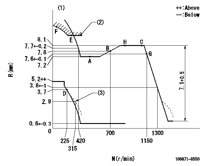
N:Pump speed
R:Rack position (mm)
(1)Tolerance for racks not indicated: +-0.05mm.
(2)Excess fuel setting for starting: SXL (N = N1)
(3)Damper spring setting
----------
SXL=8.3+-0.1mm N1=350r/min
----------
----------
SXL=8.3+-0.1mm N1=350r/min
----------
Speed control lever angle

F:Full speed
----------
----------
a=14.5deg+-5deg
----------
----------
a=14.5deg+-5deg
0000000901
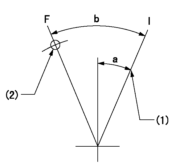
F:Full load
I:Idle
(1)Stopper bolt setting
(2)Use the hole at R = aa
----------
aa=45mm
----------
a=24deg+-5deg b=35.5deg+-3deg
----------
aa=45mm
----------
a=24deg+-5deg b=35.5deg+-3deg
Stop lever angle
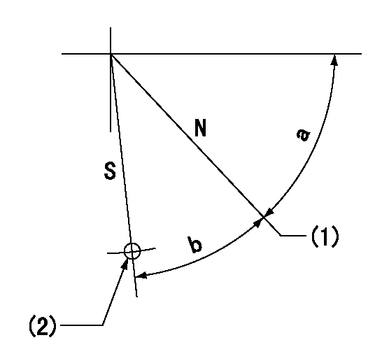
N:Pump normal
S:Stop the pump.
(1)Set stopper screw so that rack position = aa (after setting, apply red paint).
(2)Use the hole at R = bb
----------
aa=13+-1mm bb=36mm
----------
a=47deg+-5deg b=33.5deg+-5deg
----------
aa=13+-1mm bb=36mm
----------
a=47deg+-5deg b=33.5deg+-5deg
0000001501 RACK SENSOR

(VR) measurement voltage
(I) Part number of the control unit
(G) Apply red paint.
(H): End surface of the pump
1. Rack sensor adjustment (-0620)
(1)Fix the speed control lever at the full position
(2)Set the speed to N1 r/min.
(If the boost compensator is provided, apply boost pressure.)
(3)Adjust the bobbin (A) so that the rack sensor's output voltage is VR+-0.01.
(4)At that time, rack position must be Ra.
(5)Apply G at two places.
Connecting part between the joint (B) and the nut (F)
Connecting part between the joint (B) and the end surface of the pump (H)
----------
N1=900r/min Ra=8.1mm
----------
----------
N1=900r/min Ra=8.1mm
----------
0000001601 GOVERNOR TORQUE CONTROL

Dr:Torque control stroke
(A): Without torque control spring capsule
1. Adjustment procedures
(1)Procedure is the same as that for the RFD (former type), except that the positive torque control stroke must be determined at the full lever setting.
2. Procedures for adjustment
(1)Remove the torque control spring capsule.
(2)Operate the pump at approximately N1. (End of idling spring operation < N1.)
(3)Tilt the lever to the full side.
(4)Set so that R = RF.
(5)Increase the speed by pushing in the screw (attached to the bracket on the rear of the tension lever) through the adjusting window.
(6)Adjust so that the torque control stroke Dr1 can be obtained.
(7)Align N2 and N3 with the torque control spring capsule.
3. Final confirmation
(1)After final confirmation, temporarily set the load lever to N = N1, R = idling position.
(2)From this condition, increase speed to N = N4.
(3)Confirm that positive torque control stroke is Dr2.
----------
N1=500r/min N2=- N3=- N4=850r/min RF=7.2mm Dr1=0.9mm Dr2=0+0.3mm
----------
----------
N1=500r/min N2=- N3=- N4=850r/min RF=7.2mm Dr1=0.9mm Dr2=0+0.3mm
----------
Timing setting

(1)Pump vertical direction
(2)Coupling's key groove position at No 1 cylinder's beginning of injection
(3)-
(4)-
----------
----------
a=(3deg)
----------
----------
a=(3deg)
Information:
Illustration 6 g06613192
Gray locking wedge removed from ECM connector
Remove gray locking wedge from 86-pin connector to provide access to release the DT Pins.Note: Circuit U937 to be removed from pin location number 24 and transferred to pin location 73.Note: Cloth tape will need to be removed to the split in the harness main bundle.Note: The U937 wire can then be routed into the opposite branch to gain enough free length to make the connection.Note: The U939 wire removed from pin location 73 has adequate length to be loaded into location 16.
Transfer and relocate the wires as detailed in Table 2.
Reinstall the locking wedge (B) when all wires have been transferred and relocated.
Illustration 7 g06613197
View of back of ECM connector with connector cover (D) removed
Apply cloth tape to both wire branches from the main bundle of wires up the branches to the harness strain relief strap location.
Illustration 8 g06613199
Connector cover (D) reinstalled with harness secured
(1) 3S-2093 Cable Strap
(D) Connector cover
Reinstall connector cover (D) and secure the harness branches using two cable straps (1).
Use caution when re-engaging the connector with the ECM.
Tighten allen head screw (A).Note: In certain cases, U937 may require lengthening to provide adequate strain relief when relocated in pin 73.Note: Refer to "Soldered Splice","Deutsch connector", or "Sealed Mechanical Splice" for the proper way to extend circuit U937.Soldered Splice
A soldered spliced can be made to extend the wire. Soldered connection will need to be insulated using an appropriately sized adhesive head shrink sleeve.
Illustration 9 g06613210
U937 removed
Remove U937 from ECM connector.
Cut pin off end of wire.
Strip wire 7.5 mm (0.30 inch).
Illustration 10 g06613213
Additional wire soldered to circuit U937
Solder to additional wire to extend U937 and install appropriate sized adhesive head shrink sleeve.
Install pin on end of U937.
Insert U937 into pin 73.
Refer to "Procedure to Change Connector Plug Assembly Pins" for the proper method to reinstall ECM connector.Deutsch connector
Table 3
Required Parts
Qty Part Number Part Name
1 115-8109 Wire Splice Note: The deutsch connector is a field serviceable alternative to permanent splices. It is made from the same high-quality silicone elastomer as used for the Deutsch connector seals and grommets. The splice body houses a contact retention system that secures a mated pair of contacts in a compact environmentally sealed unit. This splice can also be serviced with standard deutsch connector tools.
Illustration 11 g06613218
Deutsch connector section view
Illustration 12 g06613221
Deutsch connector splice installed
Illustration 13 g06613224
Sufficient strain relief for deutsch connector
Refer to "Procedure to Change Connector Plug Assembly Pins" for the proper method to reinstall ECM connectorSealed Mechanical Splice
Table 4
Required Parts
Qty Part Number Part Name
1 136-4877 Wire Splice Note: Sealed mechanical splices have head-shrinkable, environmentally sealed sleeves.
Illustration 14 g06613205
Sealed mechanical splice
Select appropriate splice size.
Strip wire 7.5 mm (0.3 inch).
Insert stripped wire into sealed mechanical splice.
Crimp sealed mechanical splice.
Apply heat to the crimped splice until tubing re-covers and adhesive flows.
Refer to "Procedure to Change Connector Plug Assembly Pins" for the proper method to reinstall ECM connector