Information injection-pump assembly
ZEXEL
106671-8470
1066718470
HINO
220203860A
220203860a
Rating:
Cross reference number
ZEXEL
106671-8470
1066718470
HINO
220203860A
220203860a
Zexel num
Bosch num
Firm num
Name
Calibration Data:
Adjustment conditions
Test oil
1404 Test oil ISO4113 or {SAEJ967d}
1404 Test oil ISO4113 or {SAEJ967d}
Test oil temperature
degC
40
40
45
Nozzle and nozzle holder
105780-8130
Bosch type code
EFEP215A
Nozzle
105780-0050
Bosch type code
DN6TD119NP1T
Nozzle holder
105780-2090
Bosch type code
EFEP215
Opening pressure
MPa
17.2
Opening pressure
kgf/cm2
175
Injection pipe
Outer diameter - inner diameter - length (mm) mm 8-3-600
Outer diameter - inner diameter - length (mm) mm 8-3-600
Overflow valve
134424-3620
Overflow valve opening pressure
kPa
162
147
177
Overflow valve opening pressure
kgf/cm2
1.65
1.5
1.8
Tester oil delivery pressure
kPa
157
157
157
Tester oil delivery pressure
kgf/cm2
1.6
1.6
1.6
Direction of rotation (viewed from drive side)
Right R
Right R
Injection timing adjustment
Direction of rotation (viewed from drive side)
Right R
Right R
Injection order
1-4-2-6-
3-5
Pre-stroke
mm
4.5
4.44
4.5
Beginning of injection position
Drive side NO.1
Drive side NO.1
Difference between angles 1
Cal 1-4 deg. 60 59.75 60.25
Cal 1-4 deg. 60 59.75 60.25
Difference between angles 2
Cyl.1-2 deg. 120 119.75 120.25
Cyl.1-2 deg. 120 119.75 120.25
Difference between angles 3
Cal 1-6 deg. 180 179.75 180.25
Cal 1-6 deg. 180 179.75 180.25
Difference between angles 4
Cal 1-3 deg. 240 239.75 240.25
Cal 1-3 deg. 240 239.75 240.25
Difference between angles 5
Cal 1-5 deg. 300 299.75 300.25
Cal 1-5 deg. 300 299.75 300.25
Injection quantity adjustment
Adjusting point
A
Rack position
10.6
Pump speed
r/min
1150
1150
1150
Average injection quantity
mm3/st.
285.2
283.2
287.2
Max. variation between cylinders
%
0
-2
2
Basic
*
Fixing the lever
*
Boost pressure
kPa
56
56
Boost pressure
mmHg
420
420
Injection quantity adjustment_02
Adjusting point
B
Rack position
4+-0.5
Pump speed
r/min
300
300
300
Average injection quantity
mm3/st.
13
10
16
Max. variation between cylinders
%
0
-15
15
Fixing the rack
*
Boost pressure
kPa
0
0
0
Boost pressure
mmHg
0
0
0
Boost compensator adjustment
Pump speed
r/min
500
500
500
Rack position
R1-4
Boost pressure
kPa
21.3
18.6
24
Boost pressure
mmHg
160
140
180
Boost compensator adjustment_02
Pump speed
r/min
500
500
500
Rack position
R1(10.6)
Boost pressure
kPa
42.7
36
49.4
Boost pressure
mmHg
320
270
370
Timer adjustment
Pump speed
r/min
975--
Advance angle
deg.
0
0
0
Remarks
Start
Start
Timer adjustment_02
Pump speed
r/min
925
Advance angle
deg.
0.3
Timer adjustment_03
Pump speed
r/min
1150
Advance angle
deg.
2.5
2
3
Remarks
Finish
Finish
Test data Ex:
Governor adjustment
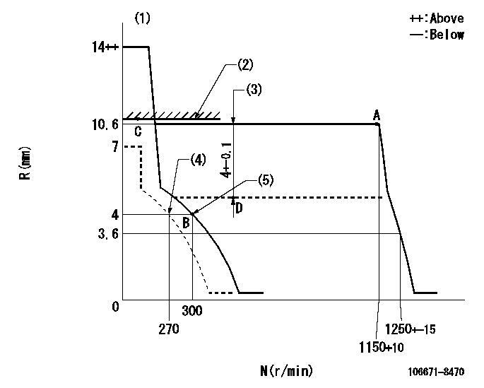
N:Pump speed
R:Rack position (mm)
(1)Target notch: K
(2)Boost compensator excessive fuel lever at operation: L1
(3)Boost compensator stroke (at N = N1)
(4)Set idle sub-spring
(5)Main spring setting
----------
K=7 L1=10.6+0.2mm N1=500r/min
----------
----------
K=7 L1=10.6+0.2mm N1=500r/min
----------
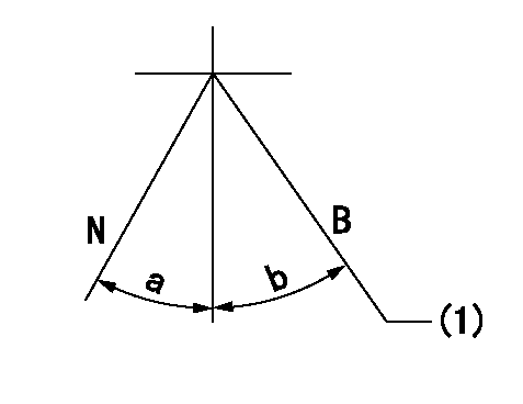
Speed control lever angle
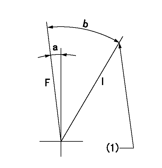
F:Full speed
I:Idle
(1)Stopper bolt setting
----------
----------
a=6deg+-5deg b=30deg+-5deg
----------
----------
a=6deg+-5deg b=30deg+-5deg
Stop lever angle
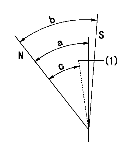
N:Pump normal
S:Stop the pump.
(1)Confirm that it returns to the non-injection position (N = aa).
----------
aa=300r/min
----------
a=53deg+-5deg b=53deg+-5deg c=49deg
----------
aa=300r/min
----------
a=53deg+-5deg b=53deg+-5deg c=49deg
0000001101
N:Normal
B:When boosted
(1)Rack position = aa
----------
aa=10.6+0.2mm
----------
a=(15deg) b=(15deg)
----------
aa=10.6+0.2mm
----------
a=(15deg) b=(15deg)
Timing setting

(1)Pump vertical direction
(2)Coupling's key groove position at No 1 cylinder's beginning of injection
(3)-
(4)-
----------
----------
a=(50deg)
----------
----------
a=(50deg)
Information:
Registering a New DEF Injector Injection Timing, Serial Number, and Part Number
Record the DEF injector trim code & part number.
Illustration 10 g06075057
(6) DEF Injector Injection Timing
(7) Part Number
Illustration 11 g06075059
(8) DEF Injector Serial Number
Record the DEF injector Serial Number.
Go to SIS.
Select "View More".
Select "Additional Service Information".
Select "C2.4, C3.3B" and "C3.8 Downloads".
Select ECU Trim Data Registration (Injector, Injection Timing, or DEF Injector).
Illustration 12 g06070579
Input the 6 or 7-digit code engine serial number. Refer to "General Information" to locate the serial number.
Click the button to select the engine.
Enter the new DEF injector part number, Serial number, and injection timing.
Illustration 13 g06075064
Once the new DEF injector Part number, Serial number and Injection timing values have been registered you may follow the DCU flashing procedure to obtain the new DPK flash file found in REHS9223, "Electronic Control Module (ECM) & Dosing Control Unit (DCU Flashing Procedure for the C2.4, C3.3B and C3.8 Engines".Note: Following the above procedure will ensure that any future DCU reflashing will flash the correct DEF injector information.New DEF Injector Install within Electronic Technician (ET)
The Caterpillar Electronic Technician (ET) is used to load injector trim files into the Engine Control Module (ECM).Replacing a DEF Injector
A new DEF Injection Timing Correction must be loaded into the DCU if an injector is replaced through Caterpillar Electronic Technician (ET).Replacing the DCU
Prior to replacing a DCU, It is recommended to download a Product Status Report for documentation of the DEF Injector. After replacing the DCU, ensure the DEF injector trim codes in the new DCU match the saved Product Status Report.
Establish communication between Cat ET and the engine ECM. Refer to Troubleshooting, "Electronic Service Tools", if necessary.
Select the following menu options on Cat ET:
Service
Calibrations
Diesel Exhaust Fluid Controller #1
Injector Code Calibration
Illustration 14 g06070577
Select Injector 1
Illustration 15 g06070578
Enter the new "DEF Injection Timing" Current Value.
Click the "Change" button.Registering (Fuel) Injection Timing Correction
The following steps are to be followed when the fuel injection timing correction procedure has been performed and the engine ecm must be updates with the new value.Note: This procedure is only performed if the crankshaft, gear case, crank gear, or flywheel is replaced. Refer to the following engine specific Special Instructions for determining Injection Timing Correction.C2.4 , M0084937C3.3B , M0084939C3.8 , M0084935
Illustration 16 g06220029
Got to SIS web. Select C2.4, C3.3B, and C3.8 Downloads.
Illustration 17 g06220033
Select ECU and DCU Trim Data Registration.
Illustration 18 g06220036
Engine Serial Number and select search. Engine Serial Number is case-sensitive.
Illustration 19 g06220038
Click the circle (indicated by red arrow) and wait for the screen to change.
Illustration 20 g06220042
Scroll down until Injection Timing Correction is displayed. Enter new value, scroll to the bottom of page, and select Register.
Once the new Injection Timing Correction value has been registered a new DPK file will need to be downloaded and flashed to the Engine ECM. Refer to , REHS9223, "Electronic Control Module (ECM) & Dosing Control Unit (DCU) Flashing Procedure for the C2.4, C3.3B and C3.8 Engines".