Information injection-pump assembly
ZEXEL
106671-8450
1066718450
HINO
220007400A
220007400a
Rating:
Cross reference number
ZEXEL
106671-8450
1066718450
HINO
220007400A
220007400a
Zexel num
Bosch num
Firm num
Name
Calibration Data:
Adjustment conditions
Test oil
1404 Test oil ISO4113 or {SAEJ967d}
1404 Test oil ISO4113 or {SAEJ967d}
Test oil temperature
degC
40
40
45
Nozzle and nozzle holder
105780-8140
Bosch type code
EF8511/9A
Nozzle
105780-0000
Bosch type code
DN12SD12T
Nozzle holder
105780-2080
Bosch type code
EF8511/9
Opening pressure
MPa
17.2
Opening pressure
kgf/cm2
175
Injection pipe
Outer diameter - inner diameter - length (mm) mm 8-3-600
Outer diameter - inner diameter - length (mm) mm 8-3-600
Overflow valve
134424-1420
Overflow valve opening pressure
kPa
162
147
177
Overflow valve opening pressure
kgf/cm2
1.65
1.5
1.8
Tester oil delivery pressure
kPa
157
157
157
Tester oil delivery pressure
kgf/cm2
1.6
1.6
1.6
Direction of rotation (viewed from drive side)
Left L
Left L
Injection timing adjustment
Direction of rotation (viewed from drive side)
Left L
Left L
Injection order
1-4-2-6-
3-5
Pre-stroke
mm
4.6
4.54
4.6
Beginning of injection position
Drive side NO.1
Drive side NO.1
Difference between angles 1
Cal 1-4 deg. 60 59.75 60.25
Cal 1-4 deg. 60 59.75 60.25
Difference between angles 2
Cyl.1-2 deg. 120 119.75 120.25
Cyl.1-2 deg. 120 119.75 120.25
Difference between angles 3
Cal 1-6 deg. 180 179.75 180.25
Cal 1-6 deg. 180 179.75 180.25
Difference between angles 4
Cal 1-3 deg. 240 239.75 240.25
Cal 1-3 deg. 240 239.75 240.25
Difference between angles 5
Cal 1-5 deg. 300 299.75 300.25
Cal 1-5 deg. 300 299.75 300.25
Injection quantity adjustment
Adjusting point
A
Rack position
7.7
Pump speed
r/min
700
700
700
Average injection quantity
mm3/st.
153
151
155
Max. variation between cylinders
%
0
-2
2
Basic
*
Fixing the lever
*
Injection quantity adjustment_02
Adjusting point
B
Rack position
7.2
Pump speed
r/min
500
500
500
Average injection quantity
mm3/st.
144
141
147
Fixing the lever
*
Injection quantity adjustment_03
Adjusting point
C
Rack position
8
Pump speed
r/min
1075
1075
1075
Average injection quantity
mm3/st.
163.6
160.6
166.6
Fixing the lever
*
Injection quantity adjustment_04
Adjusting point
D
Rack position
3.6+-0.5
Pump speed
r/min
225
225
225
Average injection quantity
mm3/st.
10.5
7.5
13.5
Max. variation between cylinders
%
0
-15
15
Fixing the rack
*
Injection quantity adjustment_05
Adjusting point
F
Rack position
8.9+-0.2
Pump speed
r/min
100
100
100
Average injection quantity
mm3/st.
160
160
200
Fixing the lever
*
Timer adjustment
Pump speed
r/min
695--
Advance angle
deg.
0
0
0
Load
1/4
Remarks
Start
Start
Timer adjustment_02
Pump speed
r/min
645
Advance angle
deg.
0.3
Load
1/4
Timer adjustment_03
Pump speed
r/min
800
Advance angle
deg.
1
0.7
1.3
Load
4/4
Timer adjustment_04
Pump speed
r/min
860
Advance angle
deg.
1
0.7
1.3
Load
3/4
Timer adjustment_05
Pump speed
r/min
1075
Advance angle
deg.
5.5
5.2
5.8
Load
4/4
Remarks
Finish
Finish
Test data Ex:
Governor adjustment
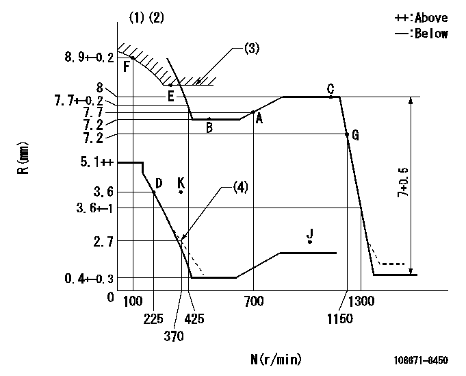
N:Pump speed
R:Rack position (mm)
(1)Tolerance for racks not indicated: +-0.05mm.
(2)Set idle at point K (N = N1, R = R1) and confirm that the rack position does not exceed R2 at point J (N = N2).
(3)Excess fuel setting for starting: SXL
(4)Damper spring setting
----------
N1=325r/min R1=3.6mm N2=1100r/min R2=2.8mm SXL=8.2+-0.1mm
----------
----------
N1=325r/min R1=3.6mm N2=1100r/min R2=2.8mm SXL=8.2+-0.1mm
----------
Speed control lever angle

F:Full speed
----------
----------
a=11.5deg+-5deg
----------
----------
a=11.5deg+-5deg
0000000901
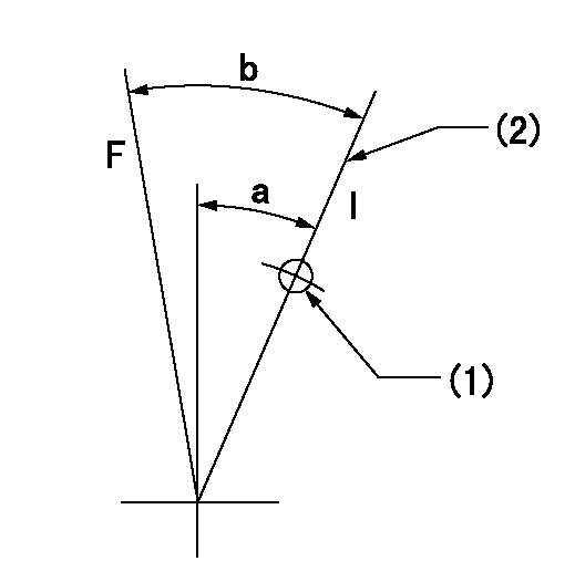
F:Full load
I:Idle
(1)Use the hole at R = aa
(2)Stopper bolt setting
----------
aa=55mm
----------
a=21deg+-5deg b=36deg+-3deg
----------
aa=55mm
----------
a=21deg+-5deg b=36deg+-3deg
Stop lever angle

N:Pump normal
S:Stop the pump.
----------
----------
a=40deg+-5deg b=64deg+-5deg
----------
----------
a=40deg+-5deg b=64deg+-5deg
0000001501 MICRO SWITCH
Adjustment of the micro-switch
Adjust the bolt to obtain the following lever position when the micro-switch is ON.
(1)Speed N1
(2)Rack position Ra
----------
N1=315r/min Ra=3.6+-0.1mm
----------
----------
N1=315r/min Ra=3.6+-0.1mm
----------
Timing setting

(1)Pump vertical direction
(2)Coupling's key groove position at No 1 cylinder's beginning of injection
(3)-
(4)-
----------
----------
a=(3deg)
----------
----------
a=(3deg)
Information:
Do not operate or work on this product unless you have read and understood the instruction and warnings in the relevant Operation and Maintenance Manuals and relevant service literature. Failure to follow the instructions or heed the warnings could result in injury or death. Proper care is your responsibility.
The following changes are adaptable to the products within the listed serial numbers, and are effective with all products after the listed serial numbers.
Illustration 1 g06489757When replacing or installing new fuel injectors, apply Nyogel® 760G lubricant on the terminals of the injector solenoid as shown in Illustration 1.The Nyogel® 760G lubricant can be ordered at the address below.https://www.nyelubricants.com/nyogel