Information injection-pump assembly
BOSCH
9 400 616 991
9400616991
ZEXEL
106671-8420
1066718420
HINO
220801510A
220801510a
Rating:
Service parts 106671-8420 INJECTION-PUMP ASSEMBLY:
1.
_
7.
COUPLING PLATE
8.
_
9.
_
11.
Nozzle and Holder
23600-1026
12.
Open Pre:MPa(Kqf/cm2)
21.6{220}
15.
NOZZLE SET
Include in #1:
106671-8420
as INJECTION-PUMP ASSEMBLY
Cross reference number
BOSCH
9 400 616 991
9400616991
ZEXEL
106671-8420
1066718420
HINO
220801510A
220801510a
Zexel num
Bosch num
Firm num
Name
106671-8420
9 400 616 991
220801510A HINO
INJECTION-PUMP ASSEMBLY
EK100 * K 14CA INJECTION PUMP ASSY PE6P,6PD PE
EK100 * K 14CA INJECTION PUMP ASSY PE6P,6PD PE
Calibration Data:
Adjustment conditions
Test oil
1404 Test oil ISO4113 or {SAEJ967d}
1404 Test oil ISO4113 or {SAEJ967d}
Test oil temperature
degC
40
40
45
Nozzle and nozzle holder
105780-8140
Bosch type code
EF8511/9A
Nozzle
105780-0000
Bosch type code
DN12SD12T
Nozzle holder
105780-2080
Bosch type code
EF8511/9
Opening pressure
MPa
17.2
Opening pressure
kgf/cm2
175
Injection pipe
Outer diameter - inner diameter - length (mm) mm 8-3-600
Outer diameter - inner diameter - length (mm) mm 8-3-600
Overflow valve
134424-0920
Overflow valve opening pressure
kPa
162
147
177
Overflow valve opening pressure
kgf/cm2
1.65
1.5
1.8
Tester oil delivery pressure
kPa
157
157
157
Tester oil delivery pressure
kgf/cm2
1.6
1.6
1.6
Direction of rotation (viewed from drive side)
Left L
Left L
Injection timing adjustment
Direction of rotation (viewed from drive side)
Left L
Left L
Injection order
1-4-2-6-
3-5
Pre-stroke
mm
3.3
3.24
3.3
Beginning of injection position
Drive side NO.1
Drive side NO.1
Difference between angles 1
Cal 1-4 deg. 60 59.75 60.25
Cal 1-4 deg. 60 59.75 60.25
Difference between angles 2
Cyl.1-2 deg. 120 119.75 120.25
Cyl.1-2 deg. 120 119.75 120.25
Difference between angles 3
Cal 1-6 deg. 180 179.75 180.25
Cal 1-6 deg. 180 179.75 180.25
Difference between angles 4
Cal 1-3 deg. 240 239.75 240.25
Cal 1-3 deg. 240 239.75 240.25
Difference between angles 5
Cal 1-5 deg. 300 299.75 300.25
Cal 1-5 deg. 300 299.75 300.25
Injection quantity adjustment
Adjusting point
A
Rack position
9.9
Pump speed
r/min
500
500
500
Average injection quantity
mm3/st.
125.5
122.5
128.5
Max. variation between cylinders
%
0
-4
4
Fixing the lever
*
Injection quantity adjustment_02
Adjusting point
B
Rack position
10.5
Pump speed
r/min
700
700
700
Average injection quantity
mm3/st.
141.2
139.2
143.2
Max. variation between cylinders
%
0
-2
2
Basic
*
Fixing the lever
*
Injection quantity adjustment_03
Adjusting point
C
Rack position
10.9
Pump speed
r/min
1150
1150
1150
Average injection quantity
mm3/st.
149.7
146.7
152.7
Max. variation between cylinders
%
0
-4
4
Fixing the lever
*
Injection quantity adjustment_04
Adjusting point
D
Rack position
7+-0.5
Pump speed
r/min
225
225
225
Average injection quantity
mm3/st.
16
13
19
Max. variation between cylinders
%
0
-15
15
Fixing the rack
*
Injection quantity adjustment_05
Adjusting point
E
Rack position
-
Pump speed
r/min
100
100
100
Average injection quantity
mm3/st.
135
135
155
Fixing the lever
*
Rack limit
*
Timer adjustment
Pump speed
r/min
700+-50
Advance angle
deg.
0
0
0
Remarks
Start
Start
Timer adjustment_02
Pump speed
r/min
900
Advance angle
deg.
1.4
0.9
1.9
Timer adjustment_03
Pump speed
r/min
1150
Advance angle
deg.
4
3.5
4.5
Remarks
Finish
Finish
Test data Ex:
Governor adjustment
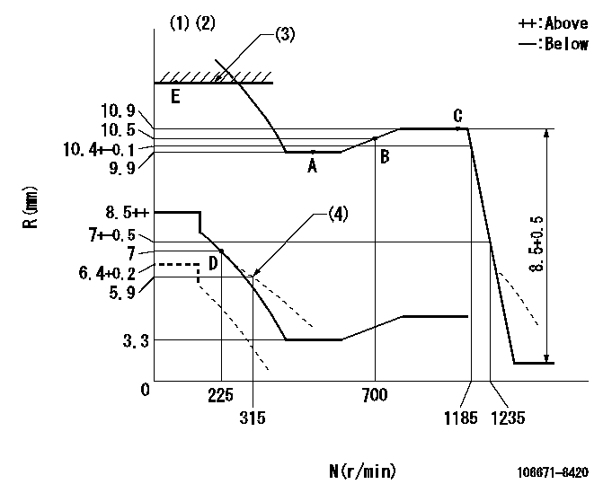
N:Pump speed
R:Rack position (mm)
(1)Tolerance for racks not indicated: +-0.05mm.
(2)Set the load lever's stop position so that R = aa (N = 0).
(3)RACK LIMIT
(4)Damper spring setting
----------
aa=6.4+0.2mm
----------
----------
aa=6.4+0.2mm
----------
Speed control lever angle

F:Full speed
----------
----------
a=15deg+-5deg
----------
----------
a=15deg+-5deg
0000000901
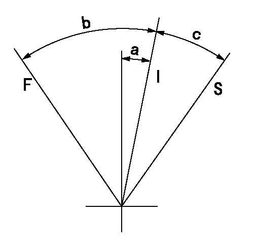
F:Full load
I:Idle
S:Stop
----------
----------
a=10deg+-5deg b=25deg+-3deg c=(14deg)+-3deg
----------
----------
a=10deg+-5deg b=25deg+-3deg c=(14deg)+-3deg
Stop lever angle
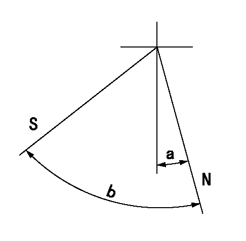
N:Pump normal
S:Stop the pump.
----------
----------
a=0deg+-5deg b=40deg+-5deg
----------
----------
a=0deg+-5deg b=40deg+-5deg
0000001501 MICRO SWITCH
Switch adjustment
Adjust the bolt so that the lower lever position is obtained when the switch is turned ON.
(1)Speed N1
(2)Rack position Ra
----------
N1=310r/min Ra=7+-0.2mm
----------
----------
N1=310r/min Ra=7+-0.2mm
----------
Timing setting

(1)Pump vertical direction
(2)Coupling's key groove position at No 1 cylinder's beginning of injection
(3)-
(4)-
----------
----------
a=(0deg)
----------
----------
a=(0deg)
Information:
Illustration 1 g01096972
Hand priming pump (1) Air purge screw (2) Fuel pressure regulating valve
Open air purge screw (1) for the fuel filter by three full turns. Do not remove the air purge screw.
Do not crank the engine continuously for more than 30 seconds. Allow the starting motor to cool for two minutes before cranking the engine again.
Start the engine. The engine should start and the engine should run smoothly. If the engine does not start after 30 seconds, allow the starting motor to cool for two minutes before attempting to start the engine again.Note: You may use the hand priming pump for the fuel filter (if equipped) instead of starting the engine and running the engine.
While the engine is running, observe air purge screw (1). When a small drop of fuel appears at the threads of the air purge screw, close and tighten air purge screw (1) .Note: There may be a noticeable change in the sound of the running engine when the air purge screw is tightened. The change in the sound of the engine is normal.Note: Failure to tighten all fittings could result in serious fuel leaks.
Clean any residual fuel from the engine components.The Engine Has Been Run Out of Fuel
Use a suitable container to catch any fuel that might spill. Clean up any spilled fuel immediately.
Do not allow dirt to enter the fuel system. Thoroughly clean the area around a fuel system component that will be
Have questions with 106671-8420?
Group cross 106671-8420 ZEXEL
Hino
106671-8420
9 400 616 991
220801510A
INJECTION-PUMP ASSEMBLY
EK100
EK100