Information injection-pump assembly
BOSCH
F 019 Z10 628
f019z10628
ZEXEL
106671-8410
1066718410
HINO
220203740A
220203740a
Rating:
Service parts 106671-8410 INJECTION-PUMP ASSEMBLY:
1.
_
7.
COUPLING PLATE
8.
_
9.
_
11.
Nozzle and Holder
236002030B
12.
Open Pre:MPa(Kqf/cm2)
19.6(200)
15.
NOZZLE SET
Include in #1:
106671-8410
as INJECTION-PUMP ASSEMBLY
Cross reference number
BOSCH
F 019 Z10 628
f019z10628
ZEXEL
106671-8410
1066718410
HINO
220203740A
220203740a
Zexel num
Bosch num
Firm num
Name
106671-8410
F 019 Z10 628
220203740A HINO
INJECTION-PUMP ASSEMBLY
EK130-T A * K
EK130-T A * K
Calibration Data:
Adjustment conditions
Test oil
1404 Test oil ISO4113 or {SAEJ967d}
1404 Test oil ISO4113 or {SAEJ967d}
Test oil temperature
degC
40
40
45
Nozzle and nozzle holder
105780-8140
Bosch type code
EF8511/9A
Nozzle
105780-0000
Bosch type code
DN12SD12T
Nozzle holder
105780-2080
Bosch type code
EF8511/9
Opening pressure
MPa
17.2
Opening pressure
kgf/cm2
175
Injection pipe
Outer diameter - inner diameter - length (mm) mm 8-3-600
Outer diameter - inner diameter - length (mm) mm 8-3-600
Overflow valve
134424-0920
Overflow valve opening pressure
kPa
162
147
177
Overflow valve opening pressure
kgf/cm2
1.65
1.5
1.8
Tester oil delivery pressure
kPa
157
157
157
Tester oil delivery pressure
kgf/cm2
1.6
1.6
1.6
Direction of rotation (viewed from drive side)
Left L
Left L
Injection timing adjustment
Direction of rotation (viewed from drive side)
Left L
Left L
Injection order
1-4-2-6-
3-5
Pre-stroke
mm
3.3
3.2
3.3
Beginning of injection position
Drive side NO.1
Drive side NO.1
Difference between angles 1
Cal 1-4 deg. 60 59.5 60.5
Cal 1-4 deg. 60 59.5 60.5
Difference between angles 2
Cyl.1-2 deg. 120 119.5 120.5
Cyl.1-2 deg. 120 119.5 120.5
Difference between angles 3
Cal 1-6 deg. 180 179.5 180.5
Cal 1-6 deg. 180 179.5 180.5
Difference between angles 4
Cal 1-3 deg. 240 239.5 240.5
Cal 1-3 deg. 240 239.5 240.5
Difference between angles 5
Cal 1-5 deg. 300 299.5 300.5
Cal 1-5 deg. 300 299.5 300.5
Injection quantity adjustment
Adjusting point
A
Rack position
9
Pump speed
r/min
900
900
900
Average injection quantity
mm3/st.
162
156
168
Max. variation between cylinders
%
0
-4
4
Fixing the rack
*
Injection quantity adjustment_02
Adjusting point
B
Rack position
9.3
Pump speed
r/min
750
750
750
Average injection quantity
mm3/st.
173.5
171.5
175.5
Max. variation between cylinders
%
0
-4
4
Basic
*
Fixing the lever
*
Injection quantity adjustment_03
Adjusting point
-
Rack position
5.4+-0.5
Pump speed
r/min
360
360
360
Average injection quantity
mm3/st.
14.8
11.8
17.8
Max. variation between cylinders
%
0
-15
15
Fixing the rack
*
Remarks
Adjust only variation between cylinders; adjust governor according to governor specifications.
Adjust only variation between cylinders; adjust governor according to governor specifications.
Timer adjustment
Pump speed
r/min
-
Advance angle
deg.
0
0
0
Remarks
Measure speed (beginning of operation).
Measure speed (beginning of operation).
Timer adjustment_02
Pump speed
r/min
-
Advance angle
deg.
4
4
4
Remarks
Measure the actual speed, stop
Measure the actual speed, stop
Test data Ex:
Governor adjustment
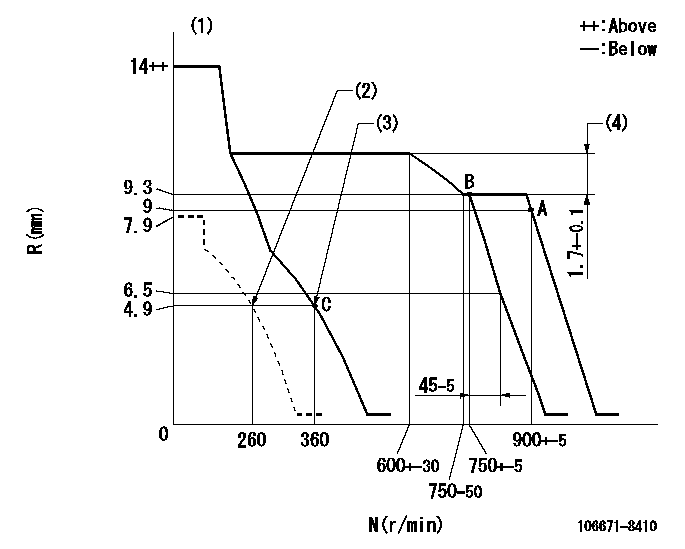
N:Pump speed
R:Rack position (mm)
(1)Target notch: K
(2)Set the idle spring.
(3)Main spring setting
(4)Rack difference between N = N1 and N = N2
----------
K=7 N1=750r/min N2=550r/min
----------
----------
K=7 N1=750r/min N2=550r/min
----------
Speed control lever angle
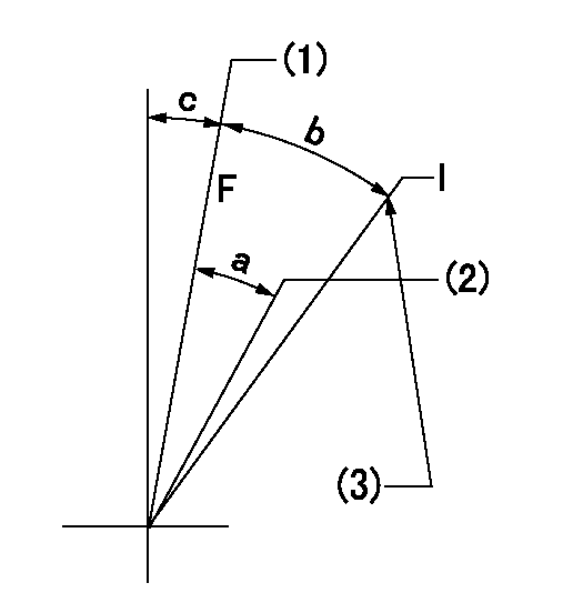
F:Full speed
I:Idle
(1)Set the pump speed at aa. ( At delivery )
(2)Set the pump speed at bb.
(3)Stopper bolt setting
----------
aa=900r/min bb=750r/min
----------
a=(4deg)+-5deg b=(19deg)+-5deg c=(3deg)+-5deg
----------
aa=900r/min bb=750r/min
----------
a=(4deg)+-5deg b=(19deg)+-5deg c=(3deg)+-5deg
Stop lever angle
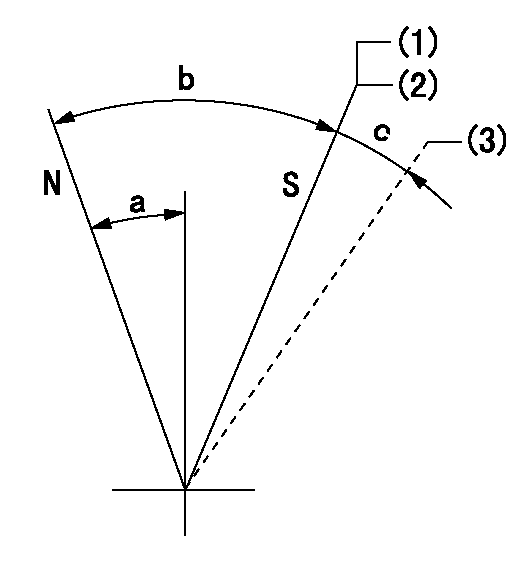
N:Pump normal
S:Stop the pump.
(1)Contacts inner stopper.
(2)Rack position aa or less, pump speed bb
(3)Contacts outer stopper.
----------
aa=4.4mm bb=0r/min
----------
a=27deg+-5deg b=53deg+-5deg c=(11deg)
----------
aa=4.4mm bb=0r/min
----------
a=27deg+-5deg b=53deg+-5deg c=(11deg)
Timing setting

(1)Pump vertical direction
(2)Coupling's key groove position at No 1 cylinder's beginning of injection
(3)-
(4)-
----------
----------
a=(0deg)
----------
----------
a=(0deg)
Information:
Reference
Refer to the electrical system schematic that is in the Electrical Schematic for the complete electrical system schematic of the engine. Refer to the Electronic Troubleshooting manual for additional information.Grounding Practices
Proper grounding for the vessel's electrical system and the engine electrical system is necessary for proper performance and reliability. Improper grounding will result in unreliable electrical circuit paths and in uncontrolled electrical circuit paths.Uncontrolled engine electrical circuit paths can result in damage to the main bearings, to the crankshaft bearing journal surfaces, and to the aluminum components.Uncontrolled electrical circuit paths can cause electrical noise which may degrade the vessel's performance and the radio performance.In order to ensure proper functioning of the vessel's electrical system and of the engine electrical system, an engine-to-frame ground strap with a direct path to the battery must be used. This is provided by a ground from the electric starting motor to the frame and to the negative battery post.The ground path must be capable of carrying any potential currents. A wire that is AWG 0 or more is recommended for the ground of the electric starting motor.The engine alternator should be grounded to the battery with a wire size that is capable of managing the full charging current of the alternator.
When jump starting an engine, the instructions in the Operation and Maintenance Manual, "Starting with Jump Start Cables" should be followed in order to properly start the engine.This engine may be equipped with a 12 volt starting system or with a 24 volt starting system. Only equal voltage for boost starting should be used. The use of a welder or of a higher voltage will damage the electrical system.
The engine has several input components which are electronic. These components require an operating voltage.This engine is tolerant of common external sources of electrical noise. Electromechanical buzzers can cause disruptions in the power supply. If electromechanical buzzers are used on the vessel, the engine electronics should be powered directly from the battery system through a dedicated relay. The engine electronics should not be powered through a common power bus with other devices that are activated by the keyswitch.Engine Electrical System
The electrical system can have three separate circuits. The three circuits are the charging circuit, the starting circuit, and the low amperage circuit. Some of the electrical system components are used in more than one circuit.The charging circuit is in operation when the engine is running. The charging circuit uses an alternator in order to create electricity. A voltage regulator in the circuit controls the electrical output in order to maintain the battery at full charge.The starting circuit is in operation when the start switch is activated.The low amperage circuit and the charging circuit are connected through the ammeter. The starting circuit is not connected through the ammeter.Starting System Components
Solenoid
Illustration 1 g00292316
Typical cross section of a solenoidA solenoid is an electromagnetic switch that performs two basic functions:
The solenoid closes the high current circuit for the electric starting motor with a low current start switch circuit.
The solenoid engages
Have questions with 106671-8410?
Group cross 106671-8410 ZEXEL
Hino
106671-8410
F 019 Z10 628
220203740A
INJECTION-PUMP ASSEMBLY
EK130-T
EK130-T