Information injection-pump assembly
ZEXEL
106671-8401
1066718401
HINO
220007071A
220007071a
Rating:
Cross reference number
ZEXEL
106671-8401
1066718401
HINO
220007071A
220007071a
Zexel num
Bosch num
Firm num
Name
Calibration Data:
Adjustment conditions
Test oil
1404 Test oil ISO4113 or {SAEJ967d}
1404 Test oil ISO4113 or {SAEJ967d}
Test oil temperature
degC
40
40
45
Nozzle and nozzle holder
105780-8140
Bosch type code
EF8511/9A
Nozzle
105780-0000
Bosch type code
DN12SD12T
Nozzle holder
105780-2080
Bosch type code
EF8511/9
Opening pressure
MPa
17.2
Opening pressure
kgf/cm2
175
Injection pipe
Outer diameter - inner diameter - length (mm) mm 8-3-600
Outer diameter - inner diameter - length (mm) mm 8-3-600
Overflow valve
134424-1720
Overflow valve opening pressure
kPa
162
147
177
Overflow valve opening pressure
kgf/cm2
1.65
1.5
1.8
Tester oil delivery pressure
kPa
157
157
157
Tester oil delivery pressure
kgf/cm2
1.6
1.6
1.6
Direction of rotation (viewed from drive side)
Left L
Left L
Injection timing adjustment
Direction of rotation (viewed from drive side)
Left L
Left L
Injection order
1-4-2-6-
3-5
Pre-stroke
mm
4.4
4.34
4.4
Beginning of injection position
Drive side NO.1
Drive side NO.1
Difference between angles 1
Cal 1-4 deg. 60 59.75 60.25
Cal 1-4 deg. 60 59.75 60.25
Difference between angles 2
Cyl.1-2 deg. 120 119.75 120.25
Cyl.1-2 deg. 120 119.75 120.25
Difference between angles 3
Cal 1-6 deg. 180 179.75 180.25
Cal 1-6 deg. 180 179.75 180.25
Difference between angles 4
Cal 1-3 deg. 240 239.75 240.25
Cal 1-3 deg. 240 239.75 240.25
Difference between angles 5
Cal 1-5 deg. 300 299.75 300.25
Cal 1-5 deg. 300 299.75 300.25
Injection quantity adjustment
Adjusting point
A
Rack position
9.2
Pump speed
r/min
650
650
650
Average injection quantity
mm3/st.
185
183
187
Max. variation between cylinders
%
0
-2
2
Basic
*
Fixing the lever
*
Boost pressure
kPa
32
32
Boost pressure
mmHg
240
240
Injection quantity adjustment_02
Adjusting point
B
Rack position
9.2
Pump speed
r/min
1000
1000
1000
Average injection quantity
mm3/st.
190.5
184.5
196.5
Max. variation between cylinders
%
0
-5
5
Fixing the lever
*
Boost pressure
kPa
32
32
Boost pressure
mmHg
240
240
Injection quantity adjustment_03
Adjusting point
D
Rack position
4.2+-0.5
Pump speed
r/min
225
225
225
Average injection quantity
mm3/st.
12.5
9.5
15.5
Max. variation between cylinders
%
0
-15
15
Fixing the rack
*
Boost pressure
kPa
0
0
0
Boost pressure
mmHg
0
0
0
Injection quantity adjustment_04
Adjusting point
E
Rack position
6.95
Pump speed
r/min
400
400
400
Average injection quantity
mm3/st.
131.5
129.5
133.5
Fixing the lever
*
Boost pressure
kPa
0
0
0
Boost pressure
mmHg
0
0
0
Boost compensator adjustment
Pump speed
r/min
650
650
650
Rack position
6.95
Boost pressure
kPa
3.3
3.3
5.3
Boost pressure
mmHg
25
25
40
Boost compensator adjustment_02
Pump speed
r/min
650
650
650
Rack position
9.2
Boost pressure
kPa
18.7
18.7
18.7
Boost pressure
mmHg
140
140
140
Timer adjustment
Pump speed
r/min
700--
Advance angle
deg.
0
0
0
Remarks
Start
Start
Timer adjustment_02
Pump speed
r/min
650
Advance angle
deg.
0.5
Timer adjustment_03
Pump speed
r/min
1000
Advance angle
deg.
3
2.7
3.3
Remarks
Finish
Finish
Test data Ex:
Governor adjustment
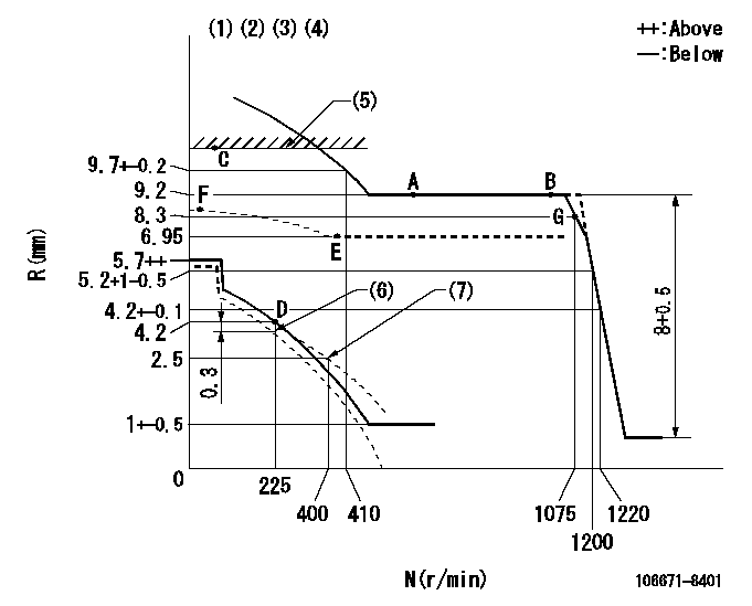
N:Pump speed
R:Rack position (mm)
(1)Lever ratio: RT
(2)Target shim dimension: TH
(3)Tolerance for racks not indicated: +-0.05mm.
(4)Deliver with positive torque control spring not operating
(5)RACK LIMIT
(6)Set idle at delivery
(7)Damper spring setting
----------
RT=0.8 TH=2.2mm
----------
----------
RT=0.8 TH=2.2mm
----------
Speed control lever angle

F:Full speed
----------
----------
a=14.5deg+-5deg
----------
----------
a=14.5deg+-5deg
0000000901
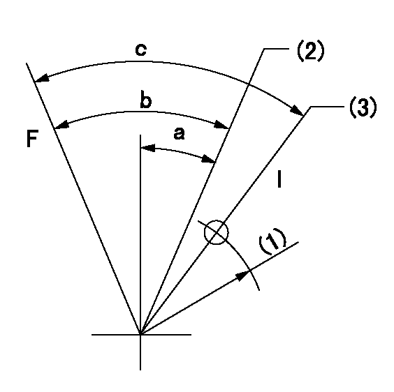
F:Full load
I:Idle
(1)R = aa
(2)Set point D
(3)At delivery
----------
aa=45mm
----------
a=25deg+-5deg b=44deg+-3deg c=46deg+-5deg
----------
aa=45mm
----------
a=25deg+-5deg b=44deg+-3deg c=46deg+-5deg
Stop lever angle

N:Pump normal
S:Stop the pump.
(1)Set stopper screw so that rack position = aa (after setting, apply red paint).
----------
aa=12+-0.1mm
----------
a=39deg+-5deg b=35deg+-5deg
----------
aa=12+-0.1mm
----------
a=39deg+-5deg b=35deg+-5deg
Timing setting

(1)Pump vertical direction
(2)Coupling's key groove position at No 1 cylinder's beginning of injection
(3)-
(4)-
----------
----------
a=(1deg)
----------
----------
a=(1deg)
Information:
Unit Injector Mechanism
Illustration 2 g01430766
Typical unit injector mechanism (17) Unit injector (18) Adjusting nut (19) Rocker arm assembly (20) CamshaftThe unit injector mechanism provides the downward force that is required to pressurize the fuel in the unit injector. When a signal is received from the ECM, the unit injector (17) injects the pressurized fuel into the combustion chamber. The camshaft gear is driven by an idler gear which is driven through the front gear train by the crankshaft gear. The gears of the front gear train that are timed must be aligned in order to provide the correct relationship between the piston and valve movement. During assembly of the front gear train, care must be taken in order to correctly align the timing marks of the gears. The camshaft has three camshaft lobes for each cylinder. Two lobes operate the inlet and exhaust valves, and one operates the unit injector mechanism. Force is transferred from the unit injector lobe on camshaft (20) through rocker arm assembly (19) to the top of the unit injector. The adjusting nut (18) allows setting of the unit injector adjustment. Refer to the Testing and Adjusting, "Electronic Unit Injector - Adjust" for the proper setting of the unit injector.Unit Injector
Illustration 3 g01332439
(21) Solenoid (22) Tappet (23) Plunger (24) Barrel (25) Nozzle assemblyOperation of the Electronic Unit Injector
The operation of the Electronic Control Unit (EUI) consists of the following four stages: Pre-injection, Injection, End of injection and Fill. Unit injectors use a plunger and barrel to pump high pressure fuel into the combustion chamber. Components of the injector include the tappet, the plunger, the barrel and nozzle assembly. Components of the nozzle assembly include the spring, the nozzle check, and a nozzle tip. The cartridge valve is made up of the following components: solenoid, armature, poppet valve and poppet spring.The injector is mounted in an injector bore in the cylinder head which has an integral fuel supply passage. The injector sleeve separates the injector from the engine coolant in the water jacket. Some engines use a stainless steel sleeve. The stainless steel sleeve fits into the cylinder head with a light press fit.
Illustration 4 g00942799
Pre-injection (A) Fuel supply pressure (B) Injection pressure (C) Moving parts (D) Mechanical movement (E) Fuel movement.Pre-injection metering starts with the injector plunger and the injector tappet at the top of the fuel injection stroke. When the plunger cavity is full of fuel, the poppet valve is in the open position and the nozzle check is in the open position. Fuel leaves the plunger cavity when the rocker arm pushes down on the tappet and the plunger. Fuel flow that is blocked by the closed nozzle check valve flows past the open poppet valve to the fuel supply passage in the cylinder head. If the solenoid is energized, the poppet valve remains open and the fuel from the plunger cavity continues flowing into the fuel supply passage.
Illustration 5 g00942798
Injection (A) Fuel supply pressure. (B) Injection pressure (C) Moving parts (D) Mechanical movement (E)