Information injection-pump assembly
ZEXEL
106671-8400
1066718400
HINO
220007070A
220007070a
Rating:
Service parts 106671-8400 INJECTION-PUMP ASSEMBLY:
1.
_
7.
COUPLING PLATE
8.
_
9.
_
11.
Nozzle and Holder
23600-1970B
12.
Open Pre:MPa(Kqf/cm2)
21.6{220}
15.
NOZZLE SET
Include in #1:
106671-8400
as INJECTION-PUMP ASSEMBLY
Cross reference number
ZEXEL
106671-8400
1066718400
HINO
220007070A
220007070a
Zexel num
Bosch num
Firm num
Name
Calibration Data:
Adjustment conditions
Test oil
1404 Test oil ISO4113 or {SAEJ967d}
1404 Test oil ISO4113 or {SAEJ967d}
Test oil temperature
degC
40
40
45
Nozzle and nozzle holder
105780-8140
Bosch type code
EF8511/9A
Nozzle
105780-0000
Bosch type code
DN12SD12T
Nozzle holder
105780-2080
Bosch type code
EF8511/9
Opening pressure
MPa
17.2
Opening pressure
kgf/cm2
175
Injection pipe
Outer diameter - inner diameter - length (mm) mm 8-3-600
Outer diameter - inner diameter - length (mm) mm 8-3-600
Overflow valve
134424-1720
Overflow valve opening pressure
kPa
162
147
177
Overflow valve opening pressure
kgf/cm2
1.65
1.5
1.8
Tester oil delivery pressure
kPa
157
157
157
Tester oil delivery pressure
kgf/cm2
1.6
1.6
1.6
Direction of rotation (viewed from drive side)
Left L
Left L
Injection timing adjustment
Direction of rotation (viewed from drive side)
Left L
Left L
Injection order
1-4-2-6-
3-5
Pre-stroke
mm
4.4
4.34
4.4
Beginning of injection position
Drive side NO.1
Drive side NO.1
Difference between angles 1
Cal 1-4 deg. 60 59.75 60.25
Cal 1-4 deg. 60 59.75 60.25
Difference between angles 2
Cyl.1-2 deg. 120 119.75 120.25
Cyl.1-2 deg. 120 119.75 120.25
Difference between angles 3
Cal 1-6 deg. 180 179.75 180.25
Cal 1-6 deg. 180 179.75 180.25
Difference between angles 4
Cal 1-3 deg. 240 239.75 240.25
Cal 1-3 deg. 240 239.75 240.25
Difference between angles 5
Cal 1-5 deg. 300 299.75 300.25
Cal 1-5 deg. 300 299.75 300.25
Injection quantity adjustment
Adjusting point
A
Rack position
9.2
Pump speed
r/min
650
650
650
Average injection quantity
mm3/st.
185
183
187
Max. variation between cylinders
%
0
-2
2
Basic
*
Fixing the lever
*
Boost pressure
kPa
32
32
Boost pressure
mmHg
240
240
Injection quantity adjustment_02
Adjusting point
B
Rack position
9.2
Pump speed
r/min
1000
1000
1000
Average injection quantity
mm3/st.
190.5
184.5
196.5
Max. variation between cylinders
%
0
-5
5
Fixing the lever
*
Boost pressure
kPa
32
32
Boost pressure
mmHg
240
240
Injection quantity adjustment_03
Adjusting point
D
Rack position
4.2+-0.5
Pump speed
r/min
225
225
225
Average injection quantity
mm3/st.
12.5
9.5
15.5
Max. variation between cylinders
%
0
-15
15
Fixing the rack
*
Boost pressure
kPa
0
0
0
Boost pressure
mmHg
0
0
0
Injection quantity adjustment_04
Adjusting point
E
Rack position
6.95
Pump speed
r/min
400
400
400
Average injection quantity
mm3/st.
131.5
129.5
133.5
Fixing the lever
*
Boost pressure
kPa
0
0
0
Boost pressure
mmHg
0
0
0
Boost compensator adjustment
Pump speed
r/min
650
650
650
Rack position
6.95
Boost pressure
kPa
3.3
3.3
5.3
Boost pressure
mmHg
25
25
40
Boost compensator adjustment_02
Pump speed
r/min
650
650
650
Rack position
9.2
Boost pressure
kPa
18.7
18.7
18.7
Boost pressure
mmHg
140
140
140
Timer adjustment
Pump speed
r/min
700--
Advance angle
deg.
0
0
0
Remarks
Start
Start
Timer adjustment_02
Pump speed
r/min
650
Advance angle
deg.
0.5
Timer adjustment_03
Pump speed
r/min
1000
Advance angle
deg.
3
2.7
3.3
Remarks
Finish
Finish
Test data Ex:
Governor adjustment
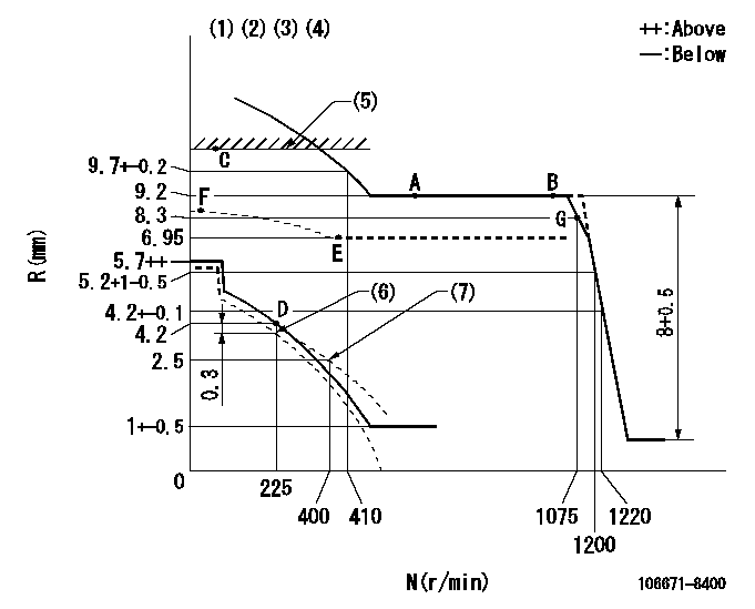
N:Pump speed
R:Rack position (mm)
(1)Lever ratio: RT
(2)Target shim dimension: TH
(3)Tolerance for racks not indicated: +-0.05mm.
(4)Deliver with positive torque control spring not operating
(5)RACK LIMIT
(6)Set idle at delivery
(7)Damper spring setting
----------
RT=0.8 TH=2.2mm
----------
----------
RT=0.8 TH=2.2mm
----------
Speed control lever angle

F:Full speed
----------
----------
a=14.5deg+-5deg
----------
----------
a=14.5deg+-5deg
0000000901
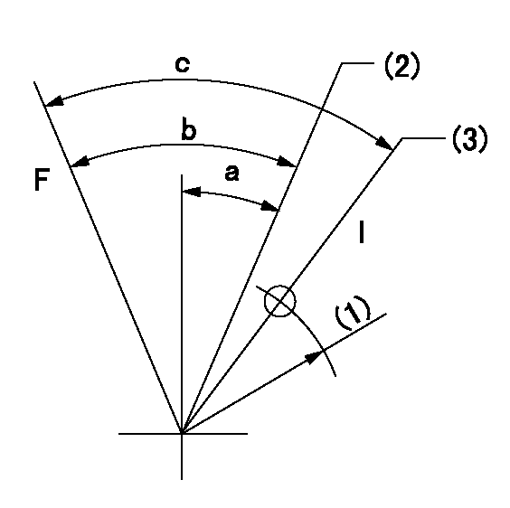
F:Full load
I:Idle
(1)R = aa
(2)Set point D
(3)At delivery
----------
aa=45mm
----------
a=25deg+-5deg b=44deg+-3deg c=46deg+-5deg
----------
aa=45mm
----------
a=25deg+-5deg b=44deg+-3deg c=46deg+-5deg
Stop lever angle
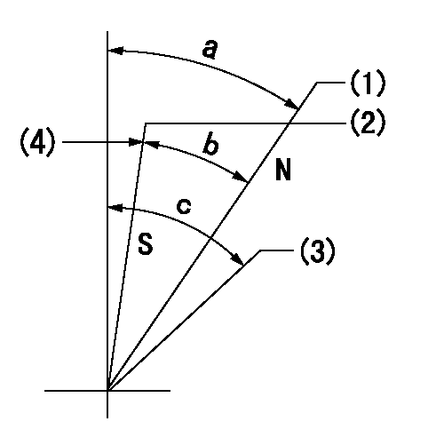
N:Engine manufacturer's normal use
S:Stop the pump.
(1)Rack position = aa
(2)Rack position bb
(3)Free (at delivery)
(4)Set the stopper bolt (apply red paint).
----------
aa=12mm bb=2.5-0.5mm
----------
a=40deg+-5deg b=30deg+-5deg c=(50deg)
----------
aa=12mm bb=2.5-0.5mm
----------
a=40deg+-5deg b=30deg+-5deg c=(50deg)
Timing setting

(1)Pump vertical direction
(2)Coupling's key groove position at No 1 cylinder's beginning of injection
(3)-
(4)-
----------
----------
a=(1deg)
----------
----------
a=(1deg)
Information:
Introduction
Do not perform any procedure in this Special Instruction until you have read this information and you understand this information.Required Parts
Table 1
Required Parts
Qty New Part Number Part Name Former Part Number
1 347-5556 Fuel Lines Kit
1 352-8532 Fuel Lines Kit 343-8867
1 352-8533 Fuel Lines Kit 310-6030 Installing the Bracket on the Line for Cylinder 5
Illustration 1 g02045118
Place the bottom portion of the clip (2) on the line for cylinder 5 before installing the line. Ensure that the grommet (1) does not become bent or misaligned.
Illustration 2 g02045093
Install the line for cylinder 5 and hand tighten the nuts on both ends of the line. Hand tighten the nut on the end that attaches to the rail (10) first and then hand tighten the nut on the other end (11) .
Illustration 3 g02045500
An alternate configuration
Illustration 4 g02045502
An alternate configuration
Install the new post (3) and the stud (8). Hand tighten the locking nut (7) on the stud.
Install the top portion of the clip (2) and ensure that the tab is tightly secured on the bottom portion of the clip. Ensure that the bolt hole on the clip and the bolt hole on the new bracket are aligned before tightening the bolt for the new bracket.
Thread the bolt (4) through the post and the clip and hand tighten the nut (5) .
Insert the threaded backing (9) on the back side of the post and hand tighten the allen head screw (6) .
Tighten the nut (10) on the end of the line for cylinder 5 that attaches to the rail and then tighten the other end (11).
Tighten the nut (7) on the stud for the post.
Tighten the nut (5) that secures the clip to the post.
Tighten the allen head screw on the spacer (9) on the back of the post.Note: Failure to correctly place the grommet (1) in the clamp could result in a failed fuel line.
