Information injection-pump assembly
ZEXEL
106671-8360
1066718360
HINO
220007090A
220007090a
Rating:
Cross reference number
ZEXEL
106671-8360
1066718360
HINO
220007090A
220007090a
Zexel num
Bosch num
Firm num
Name
Calibration Data:
Adjustment conditions
Test oil
1404 Test oil ISO4113 or {SAEJ967d}
1404 Test oil ISO4113 or {SAEJ967d}
Test oil temperature
degC
40
40
45
Nozzle and nozzle holder
105780-8140
Bosch type code
EF8511/9A
Nozzle
105780-0000
Bosch type code
DN12SD12T
Nozzle holder
105780-2080
Bosch type code
EF8511/9
Opening pressure
MPa
17.2
Opening pressure
kgf/cm2
175
Injection pipe
Outer diameter - inner diameter - length (mm) mm 8-3-600
Outer diameter - inner diameter - length (mm) mm 8-3-600
Overflow valve
134424-1420
Overflow valve opening pressure
kPa
162
147
177
Overflow valve opening pressure
kgf/cm2
1.65
1.5
1.8
Tester oil delivery pressure
kPa
157
157
157
Tester oil delivery pressure
kgf/cm2
1.6
1.6
1.6
Direction of rotation (viewed from drive side)
Left L
Left L
Injection timing adjustment
Direction of rotation (viewed from drive side)
Left L
Left L
Injection order
1-4-2-6-
3-5
Pre-stroke
mm
4.6
4.54
4.6
Beginning of injection position
Drive side NO.1
Drive side NO.1
Difference between angles 1
Cal 1-4 deg. 60 59.75 60.25
Cal 1-4 deg. 60 59.75 60.25
Difference between angles 2
Cyl.1-2 deg. 120 119.75 120.25
Cyl.1-2 deg. 120 119.75 120.25
Difference between angles 3
Cal 1-6 deg. 180 179.75 180.25
Cal 1-6 deg. 180 179.75 180.25
Difference between angles 4
Cal 1-3 deg. 240 239.75 240.25
Cal 1-3 deg. 240 239.75 240.25
Difference between angles 5
Cal 1-5 deg. 300 299.75 300.25
Cal 1-5 deg. 300 299.75 300.25
Injection quantity adjustment
Adjusting point
A
Rack position
7.2
Pump speed
r/min
500
500
500
Average injection quantity
mm3/st.
141.4
138.4
144.4
Fixing the lever
*
Injection quantity adjustment_02
Adjusting point
B
Rack position
7.5
Pump speed
r/min
700
700
700
Average injection quantity
mm3/st.
149.7
147.7
151.7
Max. variation between cylinders
%
0
-2
2
Basic
*
Fixing the lever
*
Injection quantity adjustment_03
Adjusting point
C
Rack position
7.7
Pump speed
r/min
1075
1075
1075
Average injection quantity
mm3/st.
155.8
152.8
158.8
Fixing the lever
*
Injection quantity adjustment_04
Adjusting point
D
Rack position
3.7+-0.5
Pump speed
r/min
225
225
225
Average injection quantity
mm3/st.
8.8
5.8
11.8
Max. variation between cylinders
%
0
-15
15
Fixing the rack
*
Injection quantity adjustment_05
Adjusting point
F
Rack position
-
Pump speed
r/min
100
100
100
Average injection quantity
mm3/st.
160
160
180
Fixing the lever
*
Remarks
After startup boost setting
After startup boost setting
Timer adjustment
Pump speed
r/min
695--
Advance angle
deg.
0
0
0
Load
1/4
Remarks
Start
Start
Timer adjustment_02
Pump speed
r/min
645
Advance angle
deg.
0.3
Load
1/4
Timer adjustment_03
Pump speed
r/min
800
Advance angle
deg.
1
0.7
1.3
Load
4/4
Timer adjustment_04
Pump speed
r/min
860
Advance angle
deg.
1
0.7
1.3
Load
3/4
Timer adjustment_05
Pump speed
r/min
1075
Advance angle
deg.
5.5
5.2
5.8
Load
4/4
Remarks
Finish
Finish
Test data Ex:
Governor adjustment
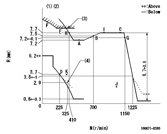
N:Pump speed
R:Rack position (mm)
(1)Tolerance for racks not indicated: +-0.05mm.
(2)Set idle at point K (N = N1, R = R1) and confirm that the injection quantity at N = N2 at point J is Q1.
(3)Excess fuel setting for starting: SXL (N = N3)
(4)Damper spring setting
----------
N1=325r/min R1=3.7mm N2=1000r/min Q1=0mm3/st SXL=8+-0.1mm N3=350r/min
----------
----------
N1=325r/min R1=3.7mm N2=1000r/min Q1=0mm3/st SXL=8+-0.1mm N3=350r/min
----------
Speed control lever angle

F:Full speed
----------
----------
a=(13deg)+-5deg
----------
----------
a=(13deg)+-5deg
0000000901
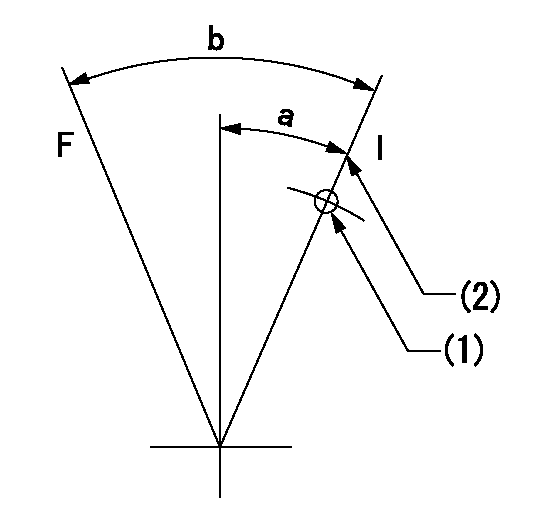
F:Full load
I:Idle
(1)Use the hole at R = aa
(2)Stopper bolt setting
----------
aa=50mm
----------
a=16deg+-5deg b=35deg+-3deg
----------
aa=50mm
----------
a=16deg+-5deg b=35deg+-3deg
Stop lever angle

N:Pump normal
S:Stop the pump.
----------
----------
a=15deg+-5deg b=64deg+-5deg
----------
----------
a=15deg+-5deg b=64deg+-5deg
0000001501 GOVERNOR TORQUE CONTROL
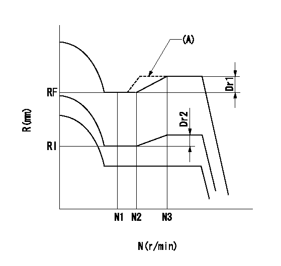
Dr:Torque control stroke
(A): Without torque control spring capsule
1. Adjustment procedures
(1)Procedure is the same as that for the RFD (former type), except that the positive torque control stroke must be determined at the full lever setting.
2. Procedures for adjustment
(1)Remove the torque control spring capsule.
(2)Operate the pump at approximately N1. (End of idling spring operation < N1.)
(3)Tilt the lever to the full side.
(4)Set so that R = RF.
(5)Increase the speed by pushing in the screw (attached to the bracket on the rear of the tension lever) through the adjusting window.
(6)Adjust so that the torque control stroke Dr1 can be obtained.
(7)Align N2 and N3 with the torque control spring capsule.
3. Final confirmation
(1)After final confirmation, temporarily set the load lever to N = N1, R = idling position.
(2)From this condition, increase speed to N = N4.
(3)Confirm that positive torque control stroke is Dr2.
----------
N1=500r/min N2=- N3=- N4=1000r/min RF=7.2mm RI=3.7mm Dr1=0.5mm Dr2=0+0.3mm
----------
----------
N1=500r/min N2=- N3=- N4=1000r/min RF=7.2mm RI=3.7mm Dr1=0.5mm Dr2=0+0.3mm
----------
0000001601 RACK SENSOR

(VR) measurement voltage
(I) Part number of the control unit
(G) Apply red paint.
(H): End surface of the pump
1. Rack limit adjustment
(1)Mount the joint (B).
(2)Select the shim (D) so that the rack limit's rack position is obtained at that time.
(3)Install the rod (E) to the block (C).
The distance between the pump end face and the rod (E) at rack limit must be L.
2. Rack sensor adjustment (-0020)
(1)Screw in the bobbin (A) until it contacts the joint (B).
(2)Fix the speed control lever at the full side.
(3)Set at speed N.
(4)Adjust the depth that the bobbin (A) is screwed in so that the control unit's rack sensor output voltage is VR+-0.01 (V), then tighten the nut (F). (If equipped with a boost compensator, perform with boost pressure applied.)
(5)Adjust the bobbin (A) so that the rack sensor's output voltage is VR+-0.01.
(6)Apply G at two places.
Connecting part between the joint (B) and the nut (F)
Connecting part between the joint (B) and the end surface of the pump (H)
----------
L=38-0.2mm N=900r/min Ra=7.7mm
----------
----------
L=38-0.2mm N=900r/min Ra=7.7mm
----------
Timing setting

(1)Pump vertical direction
(2)Coupling's key groove position at No 1 cylinder's beginning of injection
(3)-
(4)-
----------
----------
a=(3deg)
----------
----------
a=(3deg)
Information:
In the New Systems, Refilled Systems, and converted systemsEvery year: add to it hours: ever year or every 2000 hours, whichever comes first.When referring to the Service Life in table 1, use the interval that occurs first. These coolant change intervals are only achievable with annual S O S Services Level 2 coolant sampling analysis.Refer to the engine Operation and Maintenance Manual for the correct interval for replacement of the cooling system water temperature regulator.Note: For engines that require a maximum of 20% glycol, make sure that the amount of additive in the final mix is appropriate. Example of mixing a 20% glycol solution is given in Table 3.
Table 3
Example of Mixing Up a 20% Glycol Coolant (1)
Total Volume of the Cooling System Add the Following:
ELC Concentrate ELI Concentrate Water
10 Gallons 2 Gallons 0.5 Gallons 7.5 Gallons
(1) Volumes can also be in liters as long as all the volume units are consistentExtended life coolants require the one time maintenance addition of an extender at coolant service mid-life. For commercial coolants, do NOT use an extender with a coolant unless the extender has been approved by the coolant manufacturer for use with the coolant. The coolant manufacturer is responsible to ensure compatibility and acceptable performance. Failure to follow these recommendations can result in shortened cooling system component life.Conventional coolants require the maintenance addition of SCA throughout the expected life. For commercial coolants, do NOT use an SCA unless approved by the coolant supplier for use with the coolant. The coolant manufacturer is responsible to ensure compatibility and acceptable performance."ASTM D6210" require coolants that are properly dosed with SCA and that are in a properly maintained cooling system in normal service to be suitable for use for a maximum of 2 years. The suitability for use requirement is the direct responsibility of the coolant manufacturer and SCA manufacturer. Consult with the coolant and/or SCA manufacturer concerning the suitability of the products for use in a given application.Cat DEAC is fully formulated and does not require a treatment with an SCA at the initial fill.A commercial heavy-duty coolant/antifreeze that meets the "ASTM D6210"specification does not require a treatment with an SCA at the initial fill.Commercial Heavy Duty coolants that meet only "ASTM D4985" specification are not recommended for Caterpillar applications. These coolants may not provide the performance characteristics needed for heavy duty applications. Cat coolants and the coolants detailed in Table 1 and in this Chapter are formulated to offer the required performance in Cat engines. Refer to Table 1 for Cat coolants recommendations.Cat ELC, Cat ELI, Cat DEAC, Cat Extender, and Cat SCA are available in several container sizes. The availability of part numbers will vary by the region. Consult your Cat dealer.In stationary and marine engine applications that do not require protection from boiling or freezing, except as noted in Table 2, Cat ELI in water or SCA and water are acceptable.