Information injection-pump assembly
ZEXEL
106671-8354
1066718354
HINO
220007083B
220007083b

Rating:
Service parts 106671-8354 INJECTION-PUMP ASSEMBLY:
1.
_
7.
COUPLING PLATE
8.
_
9.
_
11.
Nozzle and Holder
23600-2221A
12.
Open Pre:MPa(Kqf/cm2)
14.7{150}/21.6{220}
14.
NOZZLE
Include in #1:
106671-8354
as INJECTION-PUMP ASSEMBLY
Cross reference number
ZEXEL
106671-8354
1066718354
HINO
220007083B
220007083b
Zexel num
Bosch num
Firm num
Name
Calibration Data:
Adjustment conditions
Test oil
1404 Test oil ISO4113 or {SAEJ967d}
1404 Test oil ISO4113 or {SAEJ967d}
Test oil temperature
degC
40
40
45
Nozzle and nozzle holder
105780-8140
Bosch type code
EF8511/9A
Nozzle
105780-0000
Bosch type code
DN12SD12T
Nozzle holder
105780-2080
Bosch type code
EF8511/9
Opening pressure
MPa
17.2
Opening pressure
kgf/cm2
175
Injection pipe
Outer diameter - inner diameter - length (mm) mm 8-3-600
Outer diameter - inner diameter - length (mm) mm 8-3-600
Overflow valve
134424-1420
Overflow valve opening pressure
kPa
162
147
177
Overflow valve opening pressure
kgf/cm2
1.65
1.5
1.8
Tester oil delivery pressure
kPa
157
157
157
Tester oil delivery pressure
kgf/cm2
1.6
1.6
1.6
Direction of rotation (viewed from drive side)
Left L
Left L
Injection timing adjustment
Direction of rotation (viewed from drive side)
Left L
Left L
Injection order
1-4-2-6-
3-5
Pre-stroke
mm
4.6
4.54
4.6
Beginning of injection position
Drive side NO.1
Drive side NO.1
Difference between angles 1
Cal 1-4 deg. 60 59.75 60.25
Cal 1-4 deg. 60 59.75 60.25
Difference between angles 2
Cyl.1-2 deg. 120 119.75 120.25
Cyl.1-2 deg. 120 119.75 120.25
Difference between angles 3
Cal 1-6 deg. 180 179.75 180.25
Cal 1-6 deg. 180 179.75 180.25
Difference between angles 4
Cal 1-3 deg. 240 239.75 240.25
Cal 1-3 deg. 240 239.75 240.25
Difference between angles 5
Cal 1-5 deg. 300 299.75 300.25
Cal 1-5 deg. 300 299.75 300.25
Injection quantity adjustment
Adjusting point
A
Rack position
7.7
Pump speed
r/min
700
700
700
Average injection quantity
mm3/st.
153
151
155
Max. variation between cylinders
%
0
-2
2
Basic
*
Fixing the lever
*
Injection quantity adjustment_02
Adjusting point
B
Rack position
7.2
Pump speed
r/min
500
500
500
Average injection quantity
mm3/st.
144
141
147
Fixing the lever
*
Injection quantity adjustment_03
Adjusting point
C
Rack position
7.8
Pump speed
r/min
1075
1075
1075
Average injection quantity
mm3/st.
154.5
151.5
157.5
Fixing the lever
*
Injection quantity adjustment_04
Adjusting point
D
Rack position
3.6+-0.5
Pump speed
r/min
225
225
225
Average injection quantity
mm3/st.
10.5
7.5
13.5
Max. variation between cylinders
%
0
-15
15
Fixing the rack
*
Injection quantity adjustment_05
Adjusting point
F
Rack position
8.7+-0.2
Pump speed
r/min
100
100
100
Average injection quantity
mm3/st.
158
158
198
Fixing the lever
*
Timer adjustment
Pump speed
r/min
695--
Advance angle
deg.
0
0
0
Load
1/4
Remarks
Start
Start
Timer adjustment_02
Pump speed
r/min
645
Advance angle
deg.
0.3
Load
1/4
Timer adjustment_03
Pump speed
r/min
800
Advance angle
deg.
1
0.7
1.3
Load
4/4
Timer adjustment_04
Pump speed
r/min
860
Advance angle
deg.
1
0.7
1.3
Load
3/4
Timer adjustment_05
Pump speed
r/min
1075
Advance angle
deg.
5.5
5.2
5.8
Load
4/4
Remarks
Finish
Finish
Test data Ex:
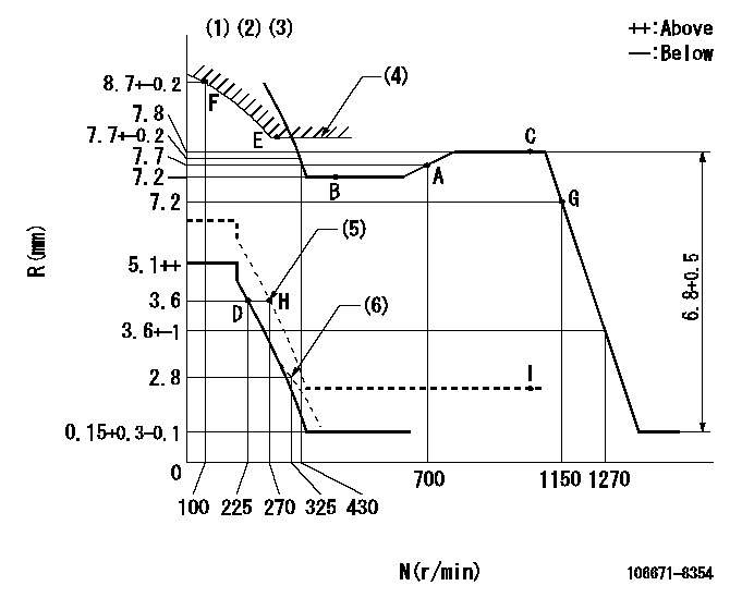
Governor adjustment

N:Pump speed
R:Rack position (mm)
(1)Lever ratio: RT
(2)Target shim dimension: TH
(3)Tolerance for racks not indicated: +-0.05mm.
(4)Excess fuel setting for starting: SXL
(5)When air cylinder is operating.
(6)Damper spring setting
----------
RT=0.8 TH=3mm SXL=8+-0.1mm
----------
----------
RT=0.8 TH=3mm SXL=8+-0.1mm
----------
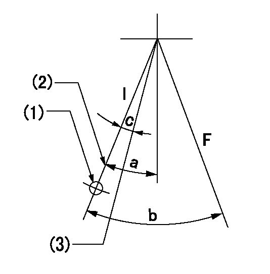
Speed control lever angle

F:Full speed
----------
----------
a=14.5deg+-5deg
----------
----------
a=14.5deg+-5deg
0000000901

F:Full load
I:Idle
(1)Use the hole at R = aa
(2)Stopper bolt setting
(3)Set point H (at air cylinder operation)
----------
aa=34mm
----------
a=26deg+-5deg b=37.5deg+-3deg c=(2deg)
----------
aa=34mm
----------
a=26deg+-5deg b=37.5deg+-3deg c=(2deg)
Stop lever angle

N:Pump normal
S:Stop the pump.
----------
----------
a=40deg+-5deg b=64deg+-5deg
----------
----------
a=40deg+-5deg b=64deg+-5deg
0000001501 GOVERNOR TORQUE CONTROL

Dr:Torque control stroke
(A): Without torque control spring capsule
1. Adjustment procedures
(1)Procedure is the same as that for the RFD (former type), except that the positive torque control stroke must be determined at the full lever setting.
2. Procedures for adjustment
(1)Remove the torque control spring capsule.
(2)Operate the pump at approximately N1. (End of idling spring operation < N1.)
(3)Tilt the lever to the full side.
(4)Set so that R = RF.
(5)Increase the speed by pushing in the screw (attached to the bracket on the rear of the tension lever) through the adjusting window.
(6)Adjust so that the torque control stroke Dr1 can be obtained.
(7)Align N2 and N3 with the torque control spring capsule.
3. Final confirmation
(1)After final confirmation, temporarily set the load lever to N = N1, R = idling position.
(2)From this condition, increase speed to N = N4.
(3)Confirm that positive torque control stroke is Dr2.
----------
N1=500r/min N2=(550)r/min N3=- N4=1000r/min RF=7.2mm Dr1=0.6mm Dr2=0+0.3mm
----------
----------
N1=500r/min N2=(550)r/min N3=- N4=1000r/min RF=7.2mm Dr1=0.6mm Dr2=0+0.3mm
----------
0000001601 LEVER

1. Air cylinder adjustment
(1)With the load lever in the idle position, temporarily set the distance between the load lever A and the air cylinder D at approximately L.
(2)Set N1 and apply P1 to the air cylinder D.
(3)Adjust set bolt (D) to obtain R1 at the same speed.
(4)Lock using nut C.
(5)Apply positive pressure several times.
(6)Confirm that the load lever A returns to the idling position N2 at pressure P2.
(7)Also at P1 confirm R1 (N1).
----------
L=(5)mm R1=3.6mm N1=270r/min N2=- P1=392+98kPa(4+1kgf/cm2) P2=0kPa(0kgf/cm2)
----------
----------
L=(5)mm R1=3.6mm N1=270r/min N2=- P1=392+98kPa(4+1kgf/cm2) P2=0kPa(0kgf/cm2)
----------
Timing setting

(1)Pump vertical direction
(2)Coupling's key groove position at No 1 cylinder's beginning of injection
(3)-
(4)-
----------
----------
a=(3deg)
----------
----------
a=(3deg)
Information:
Faulty engine coolant temperature regulators, or operating with light loads, short operation cycles, excessive idling, or operating in applications where normal operating temperature is seldom reached can contribute to excessive water in the crankcase oil. Corrosive damage, piston deposits, increased oil consumption, and other damage can result. If a complete oil analysis program is not followed or if the results are ignored, the potential for damage increases. Follow engine warmup recommendations provided in this Special Publication and/or given in your engine Operation and Maintenance Manual.
Cat Fluids
Cat fluids have been developed and tested by Cat in order to increase the performance and the life of Cat components. The quality of finished oil is dependent on the quality of the base stock, the quality of the additives and the compatibility of the base stock and additives. Cat fluids are formulated of high-quality refined oil base stocks and additives of optimal chemistry and quantity in order to provide high performance in engines and machine components. Cat fluids are used for factory fill of Cat engines and components and are offered by Cat dealers for service fills and as aftermarket products. Consult with your Cat dealer for more information on these Cat fluids.Cat recommends the use of the following Cat fluids:
Table 1
Cat Lubricants Viscosity Grade
Diesel Engine Oil-Ultra Low Sulfur (1) (2)(API CK-4) Cat DEO-ULS SAE 15W-40
SAE 10W-30
Cat DEO-ULS SYN SAE 5W-40
Cat DEO Cold Weather SAE 0W-40
Diesel Engine Oil (1)
(API CI-4/API CI-4PLUS) Cat DEO SAE 15W-40
SAE 10W-30
Multi Application Engine Oil Cat MAEO Plus (Non-Cat mixed fleets) SAE 10W-40
Diesel Engine Oil
(API CF) Cat DEO (3600 engines only) SAE 40
Pre Combustion Oil Cat PCO SAE 40
(1) Cat engine oils exceed the performance requirements of the respective API categories
(2) These oils have changed from API CJ-4 to API CK-4 early in 2017Note: Additional Cat fluids may be available.Note: Cat offers Special Application Engine Oil (SAEO), API CF-4 oil of SAE 30 and SAE 40 viscosity grades. These oils are recommended for use in 3116 and 3126 marine engines.
Table 2
Cat Grease products
Grease Cat Utility Grease
Cat Ball Bearing Grease
Cat White Assembly Grease
Table 3
Cat Engine Coolant Products
Cat Extend Life Coolants and Extenders Cat Extended Life Coolant (Cat ELC)
Cat Extended Life Inhibitor (Cat ELI)
Cat Extended Life Extender (Cat ELC Extender)
Cat Conventional Coolants and Supplemental Coolant Additives Cat Diesel Engine Antifreeze Coolant
Cat Supplemental Coolant Additive (SCA) Note: Cat fluids availability will vary by region.This information applies to Cat machines. For more lubricant recommendations see the following Special Publications:
Special Publication, SEBU6250, "Caterpillar Machine Fluid Recommendations"
Special Publication, SEBU6385, "Caterpillar On-Highway Diesel Engine Fluids Recommendations"
Special Publication, SEBU6400, "Caterpillar Gas Engine Fluids Recommendations"
Special Publication, SEBU7003, "Caterpillar 3600 Series and C280 Series Diesel Engine Fluids Recommendations"Always consult your Cat dealer in order to ensure that you have the current revision level of the publication.Note: The optimal application of the lubricants is dependent on the oil quality and the maintenance practices such as contamination control, tank management, and general handling practices.