Information injection-pump assembly
ZEXEL
106671-8292
1066718292
HINO
220006552A
220006552a
Rating:
Cross reference number
ZEXEL
106671-8292
1066718292
HINO
220006552A
220006552a
Zexel num
Bosch num
Firm num
Name
Calibration Data:
Adjustment conditions
Test oil
1404 Test oil ISO4113 or {SAEJ967d}
1404 Test oil ISO4113 or {SAEJ967d}
Test oil temperature
degC
40
40
45
Nozzle and nozzle holder
105780-8140
Bosch type code
EF8511/9A
Nozzle
105780-0000
Bosch type code
DN12SD12T
Nozzle holder
105780-2080
Bosch type code
EF8511/9
Opening pressure
MPa
17.2
Opening pressure
kgf/cm2
175
Injection pipe
Outer diameter - inner diameter - length (mm) mm 8-3-600
Outer diameter - inner diameter - length (mm) mm 8-3-600
Overflow valve
134424-1420
Overflow valve opening pressure
kPa
162
147
177
Overflow valve opening pressure
kgf/cm2
1.65
1.5
1.8
Tester oil delivery pressure
kPa
157
157
157
Tester oil delivery pressure
kgf/cm2
1.6
1.6
1.6
Direction of rotation (viewed from drive side)
Left L
Left L
Injection timing adjustment
Direction of rotation (viewed from drive side)
Left L
Left L
Injection order
1-4-2-6-
3-5
Pre-stroke
mm
4.6
4.54
4.6
Beginning of injection position
Drive side NO.1
Drive side NO.1
Difference between angles 1
Cal 1-4 deg. 60 59.75 60.25
Cal 1-4 deg. 60 59.75 60.25
Difference between angles 2
Cyl.1-2 deg. 120 119.75 120.25
Cyl.1-2 deg. 120 119.75 120.25
Difference between angles 3
Cal 1-6 deg. 180 179.75 180.25
Cal 1-6 deg. 180 179.75 180.25
Difference between angles 4
Cal 1-3 deg. 240 239.75 240.25
Cal 1-3 deg. 240 239.75 240.25
Difference between angles 5
Cal 1-5 deg. 300 299.75 300.25
Cal 1-5 deg. 300 299.75 300.25
Injection quantity adjustment
Adjusting point
A
Rack position
7.2
Pump speed
r/min
500
500
500
Average injection quantity
mm3/st.
141.4
138.4
144.4
Fixing the lever
*
Injection quantity adjustment_02
Adjusting point
B
Rack position
7.5
Pump speed
r/min
700
700
700
Average injection quantity
mm3/st.
149.7
147.7
151.7
Max. variation between cylinders
%
0
-2
2
Basic
*
Fixing the lever
*
Injection quantity adjustment_03
Adjusting point
C
Rack position
7.7
Pump speed
r/min
1075
1075
1075
Average injection quantity
mm3/st.
155.8
152.8
158.8
Fixing the lever
*
Injection quantity adjustment_04
Adjusting point
D
Rack position
3.7+-0.5
Pump speed
r/min
225
225
225
Average injection quantity
mm3/st.
8.8
5.8
11.8
Max. variation between cylinders
%
0
-15
15
Fixing the rack
*
Injection quantity adjustment_05
Adjusting point
F
Rack position
-
Pump speed
r/min
100
100
100
Average injection quantity
mm3/st.
160
160
180
Fixing the lever
*
Remarks
After startup boost setting
After startup boost setting
Timer adjustment
Pump speed
r/min
695--
Advance angle
deg.
0
0
0
Load
1/4
Remarks
Start
Start
Timer adjustment_02
Pump speed
r/min
645
Advance angle
deg.
0.3
Load
1/4
Timer adjustment_03
Pump speed
r/min
800
Advance angle
deg.
1
0.7
1.3
Load
4/4
Timer adjustment_04
Pump speed
r/min
860
Advance angle
deg.
1
0.7
1.3
Load
3/4
Timer adjustment_05
Pump speed
r/min
1075
Advance angle
deg.
5.5
5.2
5.8
Load
4/4
Remarks
Finish
Finish
Test data Ex:
Governor adjustment
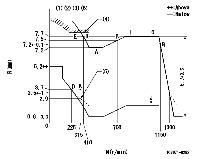
N:Pump speed
R:Rack position (mm)
(1)Lever ratio: RT
(2)Target shim dimension: TH
(3)Tolerance for racks not indicated: +-0.05mm.
(4)Excess fuel setting for starting: SXL (N = N1)
(5)Damper spring setting
(6)Set idle at point K (N = N2, R = R1) and confirm that the injection quantity at N = N3 at point J is Q1.
----------
RT=0.8 TH=2.8mm SXL=8+-0.1mm N1=350r/min N2=325r/min R1=3.7mm N3=1000r/min Q1=0mm3/st
----------
----------
RT=0.8 TH=2.8mm SXL=8+-0.1mm N1=350r/min N2=325r/min R1=3.7mm N3=1000r/min Q1=0mm3/st
----------
Speed control lever angle

F:Full speed
----------
----------
a=(12deg)+-5deg
----------
----------
a=(12deg)+-5deg
0000000901
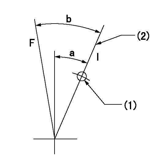
F:Full load
I:Idle
(1)Use the hole at R = aa
(2)Stopper bolt setting
----------
aa=50mm
----------
a=16deg+-5deg b=36deg+-3deg
----------
aa=50mm
----------
a=16deg+-5deg b=36deg+-3deg
Stop lever angle

N:Pump normal
S:Stop the pump.
----------
----------
a=15deg+-5deg b=64deg+-5deg
----------
----------
a=15deg+-5deg b=64deg+-5deg
0000001501 RACK SENSOR

(VR) measurement voltage
(I) Part number of the control unit
(G) Apply red paint.
(H): End surface of the pump
1. Rack sensor adjustment (-0620)
(1)Fix the speed control lever at the full position
(2)Set the speed to N1 r/min.
(If the boost compensator is provided, apply boost pressure.)
(3)Adjust the bobbin (A) so that the rack sensor's output voltage is VR+-0.01.
(4)At that time, rack position must be Ra.
(5)Apply G at two places.
Connecting part between the joint (B) and the nut (F)
Connecting part between the joint (B) and the end surface of the pump (H)
----------
N1=900r/min Ra=7.7mm
----------
----------
N1=900r/min Ra=7.7mm
----------
Timing setting

(1)Pump vertical direction
(2)Coupling's key groove position at No 1 cylinder's beginning of injection
(3)-
(4)-
----------
----------
a=(3deg)
----------
----------
a=(3deg)
Information:
Mast Cab Side Bank-Lube Points and Locations
Illustration 14 g06355954
Mast cab side bank-lube points
(A) Right Mast Pivot Pin
(B) Right Mast Raise Cylinder Upper Pin
(C) Gear Box Air Seal (Top side)
(D) Gear Box Top Lip Seal Top Air Seal (Bottom Side)
(E) Pipe Rack Upper Swing Cylinder Head End
(F) Pipe Rack Carousel Support Bearing
(G) Pipe Rack Journal Bearing
(H) Pipe Rack Journal Bearing
(J) Left Side Top Sheave Pin
(K) Right Side Top Sheave Pin
(L) Left Side Bottom Sheave Pin
(M) Right Side Bottom Sheave Pin
(N) Right Side Pipe Positioner Roller Pin
(P) Right Side Pipe Positioner Swing Pin
(R) Left Side Pipe Positioner Swing Pin
(S) Left Side Pipe Positioner Roller Pin
Table 12
Mast Cab Side Bank
Item Description Sleeve color
A Right Mast Pivot Pin Red
B Right Mast Raise Cylinder Upper Pin Red
C Gear Box Air Seal (Top side) Nut
D Gear Box Top Lip Seal Top Air Seal (Bottom Side) Red
E Pipe Rack Upper Swing Cylinder Head End Red
F Pipe Rack Carousel Support Bearing Red
G Pipe Rack Journal Bearing Red
H Pipe Rack Journal Bearing Red
J Left Side Top Sheave Pin Red
K Right Side Top Sheave Pin Red
L Left Side Bottom Sheave Pin Red
M Right Side Bottom Sheave Pin Red
N Right Side Pipe Positioner Roller Pin Red
P Right Side Pipe Positioner Swing Pin Nut
R Left Side Pipe Positioner Swing Pin Nut
S Right Side Pipe Positioner Roller Pin Red Hydraulic Break Out Wrenches (Hobo)-Lube Points
Illustration 15 g06355971
Hobo-lube points
(A) HOBO Rotate Cylinder Head End
(B) HOBO Swing Pivot Pin Top
(C) HOBO Swing Pivot Pin Bottom
(D) HOBO Swing Cylinder Rod End
(E) HOBO Clamp Slide
(F) HOBO Rotate Cylinder Rod End
(G) HOBO Clamp Cylinder Rod End
(H) HOBO Clamp Pin
Table 13
Hydraulic Break Out Wrenches (HOBO)
Item Description Sleeve color
A HOBO Rotate Cylinder Head End Nut
B HOBO Swing Pivot Pin Top Red
C HOBO Swing Pivot Pin Bottom Red
D HOBO Swing Cylinder Rod End Red
E HOBO Clamp Slide Red
F HOBO Rotate Cylinder Rod End Nut
G HOBO Clamp Cylinder Rod End Nut
H HOBO Clamp Pin Red