Information injection-pump assembly
BOSCH
9 400 613 387
9400613387
ZEXEL
106671-8220
1066718220
HINO
220203450A
220203450a
Rating:
Service parts 106671-8220 INJECTION-PUMP ASSEMBLY:
1.
_
7.
COUPLING PLATE
8.
_
9.
_
11.
Nozzle and Holder
236001561C
12.
Open Pre:MPa(Kqf/cm2)
21.6{220}
15.
NOZZLE SET
Include in #1:
106671-8220
as INJECTION-PUMP ASSEMBLY
Cross reference number
BOSCH
9 400 613 387
9400613387
ZEXEL
106671-8220
1066718220
HINO
220203450A
220203450a
Zexel num
Bosch num
Firm num
Name
106671-8220
9 400 613 387
220203450A HINO
INJECTION-PUMP ASSEMBLY
EP100-T * K 14CA INJECTION PUMP ASSY PE6P,6PD PE
EP100-T * K 14CA INJECTION PUMP ASSY PE6P,6PD PE
Calibration Data:
Adjustment conditions
Test oil
1404 Test oil ISO4113 or {SAEJ967d}
1404 Test oil ISO4113 or {SAEJ967d}
Test oil temperature
degC
40
40
45
Nozzle and nozzle holder
105780-8140
Bosch type code
EF8511/9A
Nozzle
105780-0000
Bosch type code
DN12SD12T
Nozzle holder
105780-2080
Bosch type code
EF8511/9
Opening pressure
MPa
17.2
Opening pressure
kgf/cm2
175
Injection pipe
Outer diameter - inner diameter - length (mm) mm 8-3-600
Outer diameter - inner diameter - length (mm) mm 8-3-600
Overflow valve (drive side)
134424-1720
Overflow valve opening pressure (drive side)
kPa
162
147
177
Overflow valve opening pressure (drive side)
kgf/cm2
1.65
1.5
1.8
Overflow valve (governor side)
134424-1420
Overflow valve opening pressure (governor side)
kPa
162
147
177
Overflow valve opening pressure (governor side)
kgf/cm2
1.65
1.5
1.8
Tester oil delivery pressure
kPa
157
157
157
Tester oil delivery pressure
kgf/cm2
1.6
1.6
1.6
Direction of rotation (viewed from drive side)
Right R
Right R
Injection timing adjustment
Direction of rotation (viewed from drive side)
Right R
Right R
Injection order
1-4-2-6-
3-5
Pre-stroke
mm
4.5
4.4
4.5
Beginning of injection position
Drive side NO.1
Drive side NO.1
Difference between angles 1
Cal 1-4 deg. 60 59.5 60.5
Cal 1-4 deg. 60 59.5 60.5
Difference between angles 2
Cyl.1-2 deg. 120 119.5 120.5
Cyl.1-2 deg. 120 119.5 120.5
Difference between angles 3
Cal 1-6 deg. 180 179.5 180.5
Cal 1-6 deg. 180 179.5 180.5
Difference between angles 4
Cal 1-3 deg. 240 239.5 240.5
Cal 1-3 deg. 240 239.5 240.5
Difference between angles 5
Cal 1-5 deg. 300 299.5 300.5
Cal 1-5 deg. 300 299.5 300.5
Injection quantity adjustment
Adjusting point
A
Rack position
7.6
Pump speed
r/min
1100
1100
1100
Average injection quantity
mm3/st.
110
107
113
Max. variation between cylinders
%
0
-2
2
Basic
*
Fixing the lever
*
Injection quantity adjustment_02
Adjusting point
B
Rack position
8
Pump speed
r/min
500
500
500
Average injection quantity
mm3/st.
117.5
114.5
120.5
Fixing the lever
*
Injection quantity adjustment_03
Adjusting point
C
Rack position
5.1+-0.5
Pump speed
r/min
325
325
325
Average injection quantity
mm3/st.
9.5
6.5
12.5
Max. variation between cylinders
%
0
-15
15
Fixing the rack
*
Injection quantity adjustment_04
Adjusting point
D
Rack position
-
Pump speed
r/min
100
100
100
Average injection quantity
mm3/st.
145
140
150
Fixing the lever
*
Rack limit
*
Timer adjustment
Pump speed
r/min
975--
Advance angle
deg.
0
0
0
Remarks
Start
Start
Timer adjustment_02
Pump speed
r/min
925
Advance angle
deg.
0.3
Timer adjustment_03
Pump speed
r/min
1100
Advance angle
deg.
1.8
1.3
2.3
Timer adjustment_04
Pump speed
r/min
-
Advance angle
deg.
2.5
2.5
2.5
Remarks
Measure the actual speed, stop
Measure the actual speed, stop
Test data Ex:
Governor adjustment
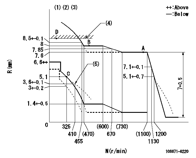
N:Pump speed
R:Rack position (mm)
(1)Lever ratio: RT
(2)Target shim dimension: TH
(3)Tolerance for racks not indicated: +-0.05mm.
(4)RACK LIMIT
(5)Damper spring setting
----------
RT=1 TH=1.9mm
----------
----------
RT=1 TH=1.9mm
----------
Speed control lever angle
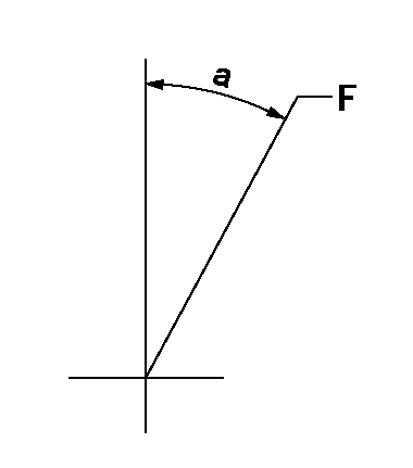
F:Full speed
----------
----------
a=6deg+-5deg
----------
----------
a=6deg+-5deg
0000000901
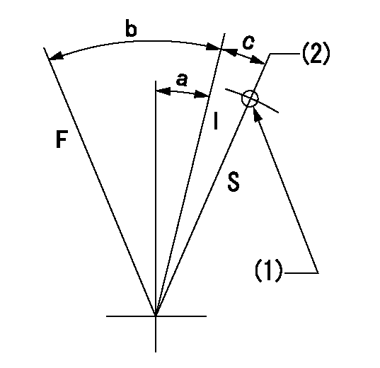
F:Full load
I:Idle
S:Stop
(1)Use the hole at R = aa
(2)Rack position = bb (speed = cc)
----------
aa=60mm bb=3+-0.2mm cc=325r/min
----------
a=10deg+-5deg b=24.5deg+-3deg c=(8deg)+-3deg
----------
aa=60mm bb=3+-0.2mm cc=325r/min
----------
a=10deg+-5deg b=24.5deg+-3deg c=(8deg)+-3deg
Stop lever angle
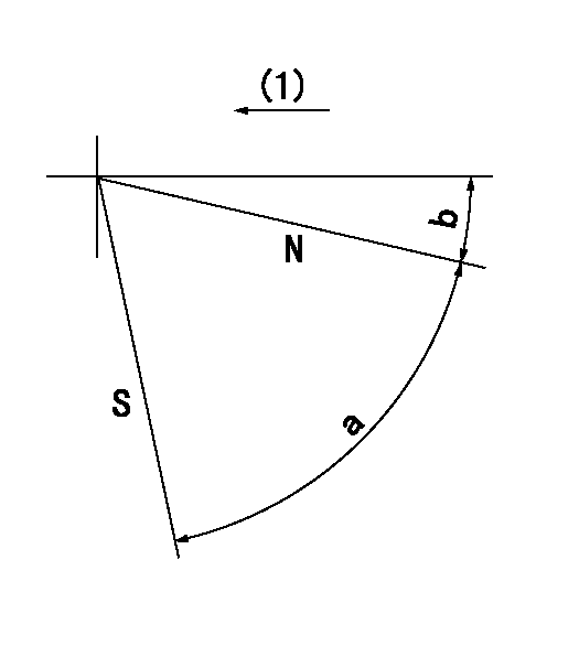
N:Pump normal
S:Stop the pump.
(1)Drive side
----------
----------
a=64deg+-5deg b=15deg+-5deg
----------
----------
a=64deg+-5deg b=15deg+-5deg
Timing setting

(1)Pump vertical direction
(2)Coupling's key groove position at No 1 cylinder's beginning of injection
(3)-
(4)-
----------
----------
a=(40deg)
----------
----------
a=(40deg)
Information:
Checking Backpressure with Manometer/Gauge
Remove the plug from the pressure tap coupling located on the manifold immediately after the engine and install a manometer or pressure gauge. Use a gauge with a minimum range of 0 to 20 kpa (0 to 80 inch of H2O).
After completely warming up the engine, run at no load, wide open throttle (W.O.T.) for 2 to 3 minutes. Record the pressure reading while the engine is running at no load, W.O.T. Repeat 2 to 3 times.
If the observed backpressure is less than 10.20 kPa (41 inch of H2O), the DPF can continue to be operated without further maintenance.
If the backpressure is greater than 10.20 kPa (41 inch of H2O) at the time of installation, contact your Caterpillar dealer. If the backpressure is greater than 10.20 kPa (41 inch of H2O) during a maintenance check, contact your Caterpillar dealer. Your Warranty Rights And Obligations
VERIFIED PRODUCT WARRANTY
Caterpillar Inc. warrants the diesel emission control system in the application for which it is sold or leased to be free from defects in design, materials, workmanship, or operation of the diesel emission control system which cause the diesel emission control system to fail to conform to the emission control performance level it was verified to, or to the requirements in the California Code of Regulations, Title 13, Sections 2700 to 2706, and 2710, for the periods of time listed below, provided there has been no abuse, neglect, or improper maintenance of your diesel emission control system, vehicle or equipment, as specified in the owners manuals. Where a warrantable condition exists, this warranty also covers the engine from damage caused by the diesel emission control system, subject to the same exclusions for abuse, neglect or improper maintenance of your vehicle or equipment. Please review your owners manual for other warranty information. Your diesel emission control system may include a core part (e.g., particulate filter, diesel oxidation catalyst, selective catalytic reduction converter) as well as hoses, connectors, a backpressure monitor (if applicable), and other emission-related assemblies. Where a warrantable condition exists, Caterpillar will repair or replace your diesel emission control system at no cost to you including diagnosis, parts, and labor.WARRANTY COVERAGE
For engines used in verified applications, the warranty period will be in years or hours or miles of operation, whichever occurs first, based on the following chart:
Table 1
Engine Type Engine Size Minimum Warranty Period
On-Road Light heavy-duty, 70 to 170 hp, Gross Vehicle Weight Rating (GVWR) less than 19,500 lbs. 5 years or 60,000 miles
Medium heavy-duty, 170 to 250 hp, GVWR from 19,500 lbs. to 33,000 lbs. 5 years or 100,000 miles
Heavy heavy-duty, exceeds 250 hp, GVWR exceeds 33,000 lbs. 5 years or 150,000 miles
Heavy heavy-duty, exceeds 250 hp, GVWR exceeds 33,000 lbs., and trucks are:
1. Typically driven over 100,000 miles per year, and
2. Have less than 300,000 miles on the odometer at the time of installation. 2 years, unlimited miles
Off-Road (includes portable engines) and Stationary Under 25 hp, and for constant speed engines rated under 50 hp with rated speeds
Have questions with 106671-8220?
Group cross 106671-8220 ZEXEL
Hino
106671-8220
9 400 613 387
220203450A
INJECTION-PUMP ASSEMBLY
EP100-T
EP100-T