Information injection-pump assembly
BOSCH
9 400 616 976
9400616976
ZEXEL
106671-8145
1066718145
HINO
220006064B
220006064b
Rating:
Service parts 106671-8145 INJECTION-PUMP ASSEMBLY:
1.
_
7.
COUPLING PLATE
8.
_
9.
_
11.
Nozzle and Holder
23600-1221A
12.
Open Pre:MPa(Kqf/cm2)
21.6{220}

15.
NOZZLE SET
Include in #1:
106671-8145
as INJECTION-PUMP ASSEMBLY
Cross reference number
BOSCH
9 400 616 976
9400616976
ZEXEL
106671-8145
1066718145
HINO
220006064B
220006064b
Zexel num
Bosch num
Firm num
Name
106671-8145
9 400 616 976
220006064B HINO
INJECTION-PUMP ASSEMBLY
EK100 * K 14CA PE6P,6PD PE
EK100 * K 14CA PE6P,6PD PE
Calibration Data:
Adjustment conditions
Test oil
1404 Test oil ISO4113 or {SAEJ967d}
1404 Test oil ISO4113 or {SAEJ967d}
Test oil temperature
degC
40
40
45
Nozzle and nozzle holder
105780-8140
Bosch type code
EF8511/9A
Nozzle
105780-0000
Bosch type code
DN12SD12T
Nozzle holder
105780-2080
Bosch type code
EF8511/9
Opening pressure
MPa
17.2
Opening pressure
kgf/cm2
175
Injection pipe
Outer diameter - inner diameter - length (mm) mm 8-3-600
Outer diameter - inner diameter - length (mm) mm 8-3-600
Overflow valve
134424-0920
Overflow valve opening pressure
kPa
162
147
177
Overflow valve opening pressure
kgf/cm2
1.65
1.5
1.8
Tester oil delivery pressure
kPa
157
157
157
Tester oil delivery pressure
kgf/cm2
1.6
1.6
1.6
Direction of rotation (viewed from drive side)
Left L
Left L
Injection timing adjustment
Direction of rotation (viewed from drive side)
Left L
Left L
Injection order
1-4-2-6-
3-5
Pre-stroke
mm
3.3
3.24
3.3
Beginning of injection position
Drive side NO.1
Drive side NO.1
Difference between angles 1
Cal 1-4 deg. 60 59.75 60.25
Cal 1-4 deg. 60 59.75 60.25
Difference between angles 2
Cyl.1-2 deg. 120 119.75 120.25
Cyl.1-2 deg. 120 119.75 120.25
Difference between angles 3
Cal 1-6 deg. 180 179.75 180.25
Cal 1-6 deg. 180 179.75 180.25
Difference between angles 4
Cal 1-3 deg. 240 239.75 240.25
Cal 1-3 deg. 240 239.75 240.25
Difference between angles 5
Cal 1-5 deg. 300 299.75 300.25
Cal 1-5 deg. 300 299.75 300.25
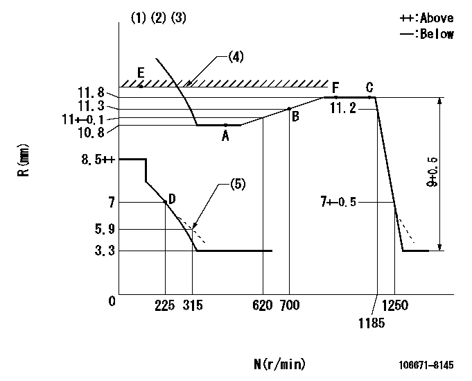
Injection quantity adjustment
Adjusting point
A
Rack position
10.8
Pump speed
r/min
500
500
500
Average injection quantity
mm3/st.
135.2
129.2
141.2
Max. variation between cylinders
%
0
-4
4
Fixing the lever
*
Injection quantity adjustment_02
Adjusting point
B
Rack position
11.3
Pump speed
r/min
700
700
700
Average injection quantity
mm3/st.
151.6
149.6
153.6
Max. variation between cylinders
%
0
-2
2
Basic
*
Fixing the lever
*
Injection quantity adjustment_03
Adjusting point
C
Rack position
11.8
Pump speed
r/min
1150
1150
1150
Average injection quantity
mm3/st.
161
155
167
Max. variation between cylinders
%
0
-4
4
Fixing the lever
*
Injection quantity adjustment_04
Adjusting point
D
Rack position
7+-0.5
Pump speed
r/min
225
225
225
Average injection quantity
mm3/st.
15
12
18
Max. variation between cylinders
%
0
-15
15
Fixing the rack
*
Injection quantity adjustment_05
Adjusting point
E
Rack position
11.9+0.2
Pump speed
r/min
100
100
100
Average injection quantity
mm3/st.
130
116
144
Fixing the lever
*
Timer adjustment
Pump speed
r/min
1000--
Advance angle
deg.
0
0
0
Remarks
Start
Start
Timer adjustment_02
Pump speed
r/min
950
Advance angle
deg.
0.5
Timer adjustment_03
Pump speed
r/min
1050
Advance angle
deg.
1.5
1
2
Timer adjustment_04
Pump speed
r/min
1150
Advance angle
deg.
4
3.7
4.3
Remarks
Finish
Finish
Test data Ex:
Governor adjustment
N:Pump speed
R:Rack position (mm)
(1)Lever ratio: RT
(2)Target shim dimension: TH
(3)Tolerance for racks not indicated: +-0.05mm.
(4)RACK LIMIT: RAL
(5)Damper spring setting
----------
RT=1 TH=2.5mm RAL=11.9+0.2mm
----------
----------
RT=1 TH=2.5mm RAL=11.9+0.2mm
----------
Speed control lever angle

F:Full speed
----------
----------
a=3deg+-5deg
----------
----------
a=3deg+-5deg
0000000901

F:Full load
I:Idle
(1)Stopper bolt setting
(2)Use the hole at R = aa
----------
aa=60mm
----------
a=15deg+-5deg b=28deg+-3deg
----------
aa=60mm
----------
a=15deg+-5deg b=28deg+-3deg
Stop lever angle
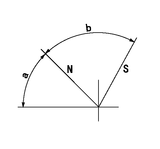
N:Pump normal
S:Stop the pump.
----------
----------
a=45deg+-5deg b=64deg+-5deg
----------
----------
a=45deg+-5deg b=64deg+-5deg
0000001501 GOVERNOR TORQUE CONTROL

Dr:Torque control stroke
(A): Without torque control spring capsule
1. Adjustment procedures
(1)Procedure is the same as that for the RFD (former type), except that the positive torque control stroke must be determined at the full lever setting.
2. Procedures for adjustment
(1)Remove the torque control spring capsule.
(2)Operate the pump at approximately N1. (End of idling spring operation < N1.)
(3)Tilt the lever to the full side.
(4)Set so that R = RF.
(5)Increase the speed by pushing in the screw (attached to the bracket on the rear of the tension lever) through the adjusting window.
(6)Adjust so that the torque control stroke Dr1 can be obtained.
(7)Align N2 and N3 with the torque control spring capsule.
3. Final confirmation
(1)After final confirmation, temporarily set the load lever to N = N1, R = idling position.
(2)From this condition, increase speed to N = N4.
(3)Confirm that positive torque control stroke is Dr2.
----------
N1=500r/min N2=- N3=- N4=1000r/min RF=10.8mm Dr1=0.8mm Dr2=0+0.3mm
----------
----------
N1=500r/min N2=- N3=- N4=1000r/min RF=10.8mm Dr1=0.8mm Dr2=0+0.3mm
----------
Timing setting

(1)Pump vertical direction
(2)Coupling's key groove position at No 1 cylinder's beginning of injection
(3)-
(4)-
----------
----------
a=(0deg)
----------
----------
a=(0deg)
Information:
Lubricant Viscosity Recommendations for Direct Injection (DI) and Precombustion Chamber (PC) engines
Refer to the minimum temperature in table 1 in order to determine the required oil viscosity for starting a cold engine. Refer to the maximum temperature in order to select the oil viscosity for engine operation at the highest ambient temperature that is anticipated.Refer to this Special Publication, "General Information for Lubricants" article for important lubricant information.Supplemental heat is recommended for cold-soaked starts below the minimum ambient temperature. Supplemental heat may be required for cold-soaked starts that are above the minimum temperature that is stated, depending on the parasitic load and other factors. Cold-soaked starts occur when the engine has not been operated for a time, allowing the oil to become more viscous in cooler ambient temperatures.For oil recommendations for Tier 4 EPA certified engines, EU stage IIIB and IV type approved engines, and Japan Step IV approved engines refer to the Special Publication, "Engine Oil" section. Refer to this Special Publication, "Lubricant Information" section for a list of all Cat engine oils.Note: Use the highest oil viscosity that is available to meet the requirement for the temperature at start-up.If ambient temperature conditions at engine start-up require the use of multigrade SAE 0W oil, SAE 0W-40 viscosity grade is preferred over SAE 0W-30.Note: Cat offers Special Application Engine Oil (SAEO), API CF oil of SAE 30 and SAE 40 viscosity grades. These oils are recommended for use in 3116 and 3126 marine engines.Note: 10W-30 is the preferred viscosity grade for the 3116, 3126, C7, C-9, and C9 diesel engines when the ambient temperature is above −18° C (0° F) and below 40° C (104° F).Note: C175 Series diesel engines require the use of multigrade SAE 40 oil: SAE 0W-40, SAE 5W-40, SAE 10W-40, or SAE 15W-40. In ambient temperatures of −9.5° C (15° F) or above, SAE 15W-40 is the preferred oil viscosity grade.If ambient temperature conditions at engine start-up require the use of multigrade SAE 0W oil, SAE 0W-40 viscosity grade is preferred over SAE 0W-30.Refer to table 1 and associated footnotes for guidance on selecting the proper oil viscosity grade for various ambient temperatures.
Table 1
Lubricant Viscosities for Ambient Temperatures for Cat Diesel Engines(1)(2)
Engine Type Oil Type and Performance Requirements Viscosity Grade °C °F
Min Max Min Max
Direct Injection (DI) and Pre Combustion (PC) Cat Cold-Weather DEO-ULS (API CK-4) SAE 0W-40 −40 40 −40 104
Cat DEO-ULS SYN (API CK-4) SAE 5W-40 −30 50 −22 122
Cat DEO-ULS (API CK-4)
Cat DEO (API CPI-4/CPI-4 PLUS) SAE 10W-30 −18 40 0 104
SAE 15W-40 −10 50 14 122
Pre Combustion (PC) only Cat PCO SAE 40 5 50 41 122
(1) Refer to Special Publication, SEBU6251, "Engine Oil", for information on the recommended and required engine oils for Tier 4 emissions certified engines.
(2) Commercial oils of viscosity grades that are not included in this table may be used if they are per Cat ECF specifications. Refer to the “Cat Engine Crankcase Fluids (ECF) Definitions” table in this Special Publication, "Engine Oil" for more information. Commercial oils
Have questions with 106671-8145?
Group cross 106671-8145 ZEXEL
Hino
106671-8145
9 400 616 976
220006064B
INJECTION-PUMP ASSEMBLY
EK100
EK100