Information injection-pump assembly
ZEXEL
106671-8132
1066718132
HINO
220203163A
220203163a
Rating:
Cross reference number
ZEXEL
106671-8132
1066718132
HINO
220203163A
220203163a
Zexel num
Bosch num
Firm num
Name
Calibration Data:
Adjustment conditions
Test oil
1404 Test oil ISO4113 or {SAEJ967d}
1404 Test oil ISO4113 or {SAEJ967d}
Test oil temperature
degC
40
40
45
Nozzle and nozzle holder
105780-8140
Bosch type code
EF8511/9A
Nozzle
105780-0000
Bosch type code
DN12SD12T
Nozzle holder
105780-2080
Bosch type code
EF8511/9
Opening pressure
MPa
17.2
Opening pressure
kgf/cm2
175
Injection pipe
Outer diameter - inner diameter - length (mm) mm 8-3-600
Outer diameter - inner diameter - length (mm) mm 8-3-600
Overflow valve (drive side)
134424-2020
Overflow valve opening pressure (drive side)
kPa
162
147
177
Overflow valve opening pressure (drive side)
kgf/cm2
1.65
1.5
1.8
Overflow valve (governor side)
134424-2120
Overflow valve opening pressure (governor side)
kPa
162
147
177
Overflow valve opening pressure (governor side)
kgf/cm2
1.65
1.5
1.8
Tester oil delivery pressure
kPa
157
157
157
Tester oil delivery pressure
kgf/cm2
1.6
1.6
1.6
Direction of rotation (viewed from drive side)
Right R
Right R
Injection timing adjustment
Direction of rotation (viewed from drive side)
Right R
Right R
Injection order
1-4-2-6-
3-5
Pre-stroke
mm
4.1
4.04
4.1
Beginning of injection position
Drive side NO.1
Drive side NO.1
Difference between angles 1
Cal 1-4 deg. 60 59.75 60.25
Cal 1-4 deg. 60 59.75 60.25
Difference between angles 2
Cyl.1-2 deg. 120 119.75 120.25
Cyl.1-2 deg. 120 119.75 120.25
Difference between angles 3
Cal 1-6 deg. 180 179.75 180.25
Cal 1-6 deg. 180 179.75 180.25
Difference between angles 4
Cal 1-3 deg. 240 239.75 240.25
Cal 1-3 deg. 240 239.75 240.25
Difference between angles 5
Cal 1-5 deg. 300 299.75 300.25
Cal 1-5 deg. 300 299.75 300.25
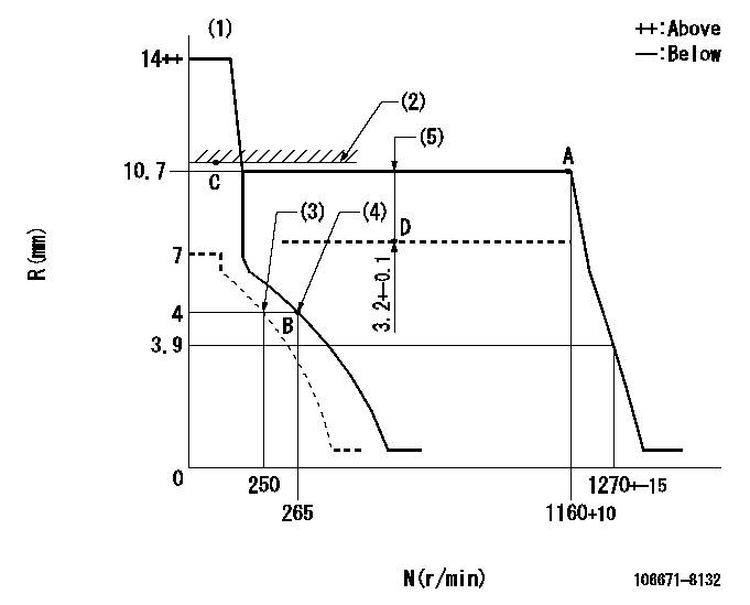
Injection quantity adjustment
Adjusting point
A
Rack position
10.7
Pump speed
r/min
1160
1160
1160
Average injection quantity
mm3/st.
179.5
177.5
181.5
Max. variation between cylinders
%
0
-2
2
Basic
*
Fixing the lever
*
Boost pressure
kPa
90.6
90.6
Boost pressure
mmHg
680
680
Injection quantity adjustment_02
Adjusting point
B
Rack position
4+-0.5
Pump speed
r/min
265
265
265
Average injection quantity
mm3/st.
12.5
11
14
Max. variation between cylinders
%
0
-15
15
Fixing the rack
*
Boost pressure
kPa
0
0
0
Boost pressure
mmHg
0
0
0
Boost compensator adjustment
Pump speed
r/min
500
500
500
Rack position
R1-3.2
Boost pressure
kPa
20
17.3
22.7
Boost pressure
mmHg
150
130
170
Boost compensator adjustment_02
Pump speed
r/min
500
500
500
Rack position
R1(10.7)
Boost pressure
kPa
80
76
84
Boost pressure
mmHg
600
570
630
Timer adjustment
Pump speed
r/min
975--
Advance angle
deg.
0
0
0
Remarks
Start
Start
Timer adjustment_02
Pump speed
r/min
925
Advance angle
deg.
0.3
Timer adjustment_03
Pump speed
r/min
1150
Advance angle
deg.
2.5
2.2
2.8
Remarks
Finish
Finish
Test data Ex:
Governor adjustment
N:Pump speed
R:Rack position (mm)
(1)Target notch: K
(2)Boost compensator excessive fuel lever at operation: L1
(3)Set idle sub-spring
(4)Main spring setting
(5)Boost compensator stroke
----------
K=10 L1=10.7+0.2mm
----------
----------
K=10 L1=10.7+0.2mm
----------
Speed control lever angle

F:Full speed
I:Idle
(1)Stopper bolt setting
----------
----------
a=(10deg)+-5deg b=(31deg)+-5deg
----------
----------
a=(10deg)+-5deg b=(31deg)+-5deg
Stop lever angle

N:Pump normal
S:Stop the pump.
----------
----------
a=27deg+-5deg b=53deg+-5deg
----------
----------
a=27deg+-5deg b=53deg+-5deg
0000001101
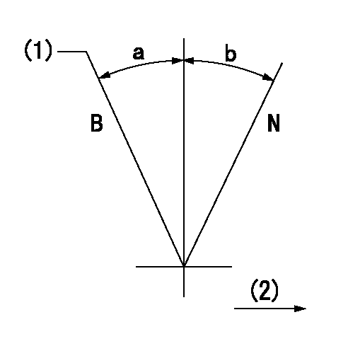
N:Normal
B:When boosted
(1)Rack position = aa
(2)Drive side
----------
aa=10.7+0.2mm
----------
a=(15deg) b=(15deg)
----------
aa=10.7+0.2mm
----------
a=(15deg) b=(15deg)
Timing setting

(1)Pump vertical direction
(2)Coupling's key groove position at No 1 cylinder's beginning of injection
(3)-
(4)-
----------
----------
a=(40deg)
----------
----------
a=(40deg)
Information:
Operation Description:Power to the ECM can fail due to an open circuit in the wire, or a blown fuse. A fuse is blown out as a result of an overloaded circuit. For example, the +battery connection is shorted to ground.Test Step 1. CHECK THE ECM FOR POWER AND GROUND.At the ECM, measure the voltage from contact 1 to contact 2. Expected Result:The voltage is system voltage.Results:
OK - The voltage is system voltage. The power supply circuit to the ECM is correct. STOP
NOT OK - The voltage is not system voltage. Proceed to Test Step 2.Test Step 2. CHECK THE FUSEWhenever the machine's electronic components fail to function, check the appropriate fuse for the ECM.
Check the fuse for the ECM.Expected Result:The fuse is correct.Results:
YES - The fuse is correct. Proceed to Test Step 3.
NO - The fuse is not correct.Repair: Replace the blown fuse or reset the circuit breaker. Observe the machine for a recurrence of the problem. If the problem persists, the reason for the blown fuse must be isolated and corrected.STOPTest Step 3. CHECK THE POWER WIRE TO THE ECM.
Turn the key start switch and the disconnect switch to the OFF position.
At the fuse, connect the lead from the multimeter to wire 113-RD.
At the ECM, connect the other lead from the multimeter to connector contact 1 and measure the resistance.Expected Result:The resistance is less than 5 ohms.Results:
OK - The resistance is less than 5 ohms. The wiring circuit is correct. Proceed to Test Step 4.
NOT OK - The resistance measurement is greater than 5000 ohms. The wiring has an open circuit.Repair: Repair the wiring harness or replace the wiring harness. STOPTest Step 4. CHECK THE ECM GROUND CONNECTIONS.
The keyswitch and the disconnect switch remain in the OFF position.
At the ECM, measure the resistance from connector contact 2 to frame ground.Expected Result:The resistance is less than 5 ohms.Results:
OK - The resistance is less than 5 ohms. The ground circuit is correct. The ECM may have failed. This is unlikely. Perform this entire procedure again. If the problem remains, the ECM may need to be replaced. Contact your dealerships for possible consultation with Caterpillar. This consultation may greatly reduce repair time.STOP
NOT OK - The resistance is greater than 5000 ohms. The ground circuit has failed.Repair: The ground circuit has failed. Repair the wiring harness or replace the wiring harness.STOP