Information injection-pump assembly
ZEXEL
106671-8131
1066718131
HINO
220203162A
220203162a
Rating:
Cross reference number
ZEXEL
106671-8131
1066718131
HINO
220203162A
220203162a
Zexel num
Bosch num
Firm num
Name
Calibration Data:
Adjustment conditions
Test oil
1404 Test oil ISO4113 or {SAEJ967d}
1404 Test oil ISO4113 or {SAEJ967d}
Test oil temperature
degC
40
40
45
Nozzle and nozzle holder
105780-8140
Bosch type code
EF8511/9A
Nozzle
105780-0000
Bosch type code
DN12SD12T
Nozzle holder
105780-2080
Bosch type code
EF8511/9
Opening pressure
MPa
17.2
Opening pressure
kgf/cm2
175
Injection pipe
Outer diameter - inner diameter - length (mm) mm 8-3-600
Outer diameter - inner diameter - length (mm) mm 8-3-600
Overflow valve (drive side)
134424-2020
Overflow valve opening pressure (drive side)
kPa
162
147
177
Overflow valve opening pressure (drive side)
kgf/cm2
1.65
1.5
1.8
Overflow valve (governor side)
134424-2120
Overflow valve opening pressure (governor side)
kPa
162
147
177
Overflow valve opening pressure (governor side)
kgf/cm2
1.65
1.5
1.8
Tester oil delivery pressure
kPa
157
157
157
Tester oil delivery pressure
kgf/cm2
1.6
1.6
1.6
Direction of rotation (viewed from drive side)
Right R
Right R
Injection timing adjustment
Direction of rotation (viewed from drive side)
Right R
Right R
Injection order
1-4-2-6-
3-5
Pre-stroke
mm
4.1
4.04
4.1
Beginning of injection position
Drive side NO.1
Drive side NO.1
Difference between angles 1
Cal 1-4 deg. 60 59.75 60.25
Cal 1-4 deg. 60 59.75 60.25
Difference between angles 2
Cyl.1-2 deg. 120 119.75 120.25
Cyl.1-2 deg. 120 119.75 120.25
Difference between angles 3
Cal 1-6 deg. 180 179.75 180.25
Cal 1-6 deg. 180 179.75 180.25
Difference between angles 4
Cal 1-3 deg. 240 239.75 240.25
Cal 1-3 deg. 240 239.75 240.25
Difference between angles 5
Cal 1-5 deg. 300 299.75 300.25
Cal 1-5 deg. 300 299.75 300.25
Injection quantity adjustment
Adjusting point
A
Rack position
11.2
Pump speed
r/min
1160
1160
1160
Average injection quantity
mm3/st.
179.5
177.5
181.5
Max. variation between cylinders
%
0
-2
2
Basic
*
Fixing the lever
*
Boost pressure
kPa
56
56
Boost pressure
mmHg
420
420
Injection quantity adjustment_02
Adjusting point
B
Rack position
4.5+-0.5
Pump speed
r/min
265
265
265
Average injection quantity
mm3/st.
12.5
11
14
Max. variation between cylinders
%
0
-15
15
Fixing the rack
*
Boost pressure
kPa
0
0
0
Boost pressure
mmHg
0
0
0
Boost compensator adjustment
Pump speed
r/min
500
500
500
Rack position
R1-3.9
Boost pressure
kPa
21.3
18.6
24
Boost pressure
mmHg
160
140
180
Boost compensator adjustment_02
Pump speed
r/min
500
500
500
Rack position
R1(11.2)
Boost pressure
kPa
42.7
36
49.4
Boost pressure
mmHg
320
270
370
Timer adjustment
Pump speed
r/min
975--
Advance angle
deg.
0
0
0
Remarks
Start
Start
Timer adjustment_02
Pump speed
r/min
925
Advance angle
deg.
0.3
Timer adjustment_03
Pump speed
r/min
1150
Advance angle
deg.
2.5
2.2
2.8
Remarks
Finish
Finish
Test data Ex:
Governor adjustment
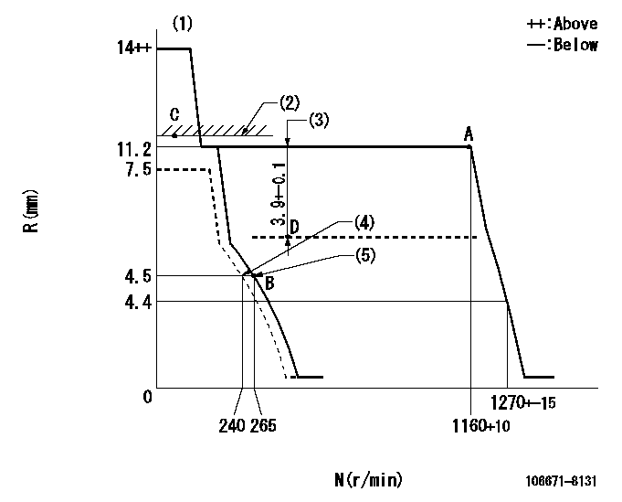
N:Pump speed
R:Rack position (mm)
(1)Target notch: K
(2)Boost compensator excessive fuel lever at operation: L1
(3)Boost compensator stroke
(4)Set idle sub-spring
(5)Main spring setting
----------
K=10 L1=11.2+0.2mm
----------
----------
K=10 L1=11.2+0.2mm
----------
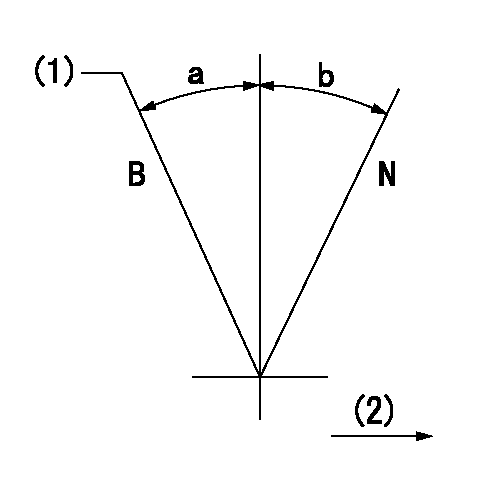
Speed control lever angle

F:Full speed
I:Idle
(1)Stopper bolt setting
----------
----------
a=(10deg)+-5deg b=(31deg)+-5deg
----------
----------
a=(10deg)+-5deg b=(31deg)+-5deg
Stop lever angle

N:Pump normal
S:Stop the pump.
----------
----------
a=27deg+-5deg b=53deg+-5deg
----------
----------
a=27deg+-5deg b=53deg+-5deg
0000001101
N:Normal
B:When boosted
(1)Rack position = aa
(2)Drive side
----------
aa=11.2+0.2mm
----------
a=(15deg) b=(15deg)
----------
aa=11.2+0.2mm
----------
a=(15deg) b=(15deg)
Timing setting

(1)Pump vertical direction
(2)Coupling's key groove position at No 1 cylinder's beginning of injection
(3)-
(4)-
----------
----------
a=(40deg)
----------
----------
a=(40deg)
Information:
Requirements For The ECM
The Electronic Control Module (ECM) for the Diesel Particulate Filter Monitor System is powered by either a +12 VDC or +24 VDC nominal battery. Refer to Table 1 for the limits for the voltage for the ECM. Refer to Illustration There is one 5 VDC +/-0.25 VDC at 500 mA auxiliary Power Supply on the ECM, routed to the machine pin group. A single return pin is used for this power supply. An "AD" channel monitors this power supply. The ECM internal power supply will provide +5 VDC for external sensor use. Refer to Illustration 1.
Illustration 1 g01340837
Illustration 2 displays mounting the Diesel Particulate Filter Monitor System to the ECM.
Illustration 2 g01340267
Table 1
Power Supply Requirements
Requirements for 12 VDC or 24 VDC system Value Notes
Operating Minimum Voltage +9V Minimum continuous operating voltage without damage to the ECM
Operating Minimum Voltage +32V Maximum continuous operating voltage without damage to the ECM
Overvoltage Maximum (two minutes continuous) +80V At 25 °C (77 °F)
Reverse Voltage (one hours) -32V
85 °C (185 °F)
power up voltage for the ECM +9V Minimum voltage for the ECM in order to run internally. Operating the engine at this voltage will cause damage to the ECM.
Cranking Voltage
Maximum current draw with key switch off 10mA
Maximum current draw with 0 engine speed and no loads being driven 500mA
Maximum continuous operating current draw 10A This is highly dependent upon the number and type of loads driven by the ECM.
Recommended Battery Fuse size 15A Programming For The ECM
The ECM is flash programmed via the Customer Data Link (CDL) with the service tool.Key Switch For The ECM
The ECM Key Switch provides the ability to shut down the ECM via a low current switch. The ECM Key Switch also increases the life of the batteries by shutting the ECM off. The Key Switch also allows operators to remotely power off the ECM. The Key Switch controls when the ECM powers up. With the Key Switch "OFF", the ECM current draw will not exceed 10mA.Connector For The ECM
The ECM uses a 70 pin connector to connect to the OEM vehicle wiring harness. The ECM Connector Screw torque should be 6 1 N m (4 0.7 lb ft)Connector Wire Gauge Size For The ECM
The battery positive and negative connections must be made with 14 gauge SAE J1128 type GXL wire for the Deutsch stamped and formed terminal or the Deutsch solid terminal. All other connections may be16 gauge or 18 gauge SAE J1128 type SXL or 14, 16 or 18 gauge SAE J1128 type GXL (or equivalent wire).For most components on the engine an 18 gauge wire has sufficient current capacity, however, many applications will benefit from the increased reliability and durability of 16 gauge