Information injection-pump assembly
ZEXEL
106671-8130
1066718130
HINO
220203161A
220203161a
Rating:
Cross reference number
ZEXEL
106671-8130
1066718130
HINO
220203161A
220203161a
Zexel num
Bosch num
Firm num
Name
Calibration Data:
Adjustment conditions
Test oil
1404 Test oil ISO4113 or {SAEJ967d}
1404 Test oil ISO4113 or {SAEJ967d}
Test oil temperature
degC
40
40
45
Nozzle and nozzle holder
105780-8140
Bosch type code
EF8511/9A
Nozzle
105780-0000
Bosch type code
DN12SD12T
Nozzle holder
105780-2080
Bosch type code
EF8511/9
Opening pressure
MPa
17.2
Opening pressure
kgf/cm2
175
Injection pipe
Outer diameter - inner diameter - length (mm) mm 8-3-600
Outer diameter - inner diameter - length (mm) mm 8-3-600
Overflow valve (drive side)
134424-2020
Overflow valve opening pressure (drive side)
kPa
162
147
177
Overflow valve opening pressure (drive side)
kgf/cm2
1.65
1.5
1.8
Overflow valve (governor side)
134424-2120
Overflow valve opening pressure (governor side)
kPa
162
147
177
Overflow valve opening pressure (governor side)
kgf/cm2
1.65
1.5
1.8
Tester oil delivery pressure
kPa
157
157
157
Tester oil delivery pressure
kgf/cm2
1.6
1.6
1.6
Direction of rotation (viewed from drive side)
Right R
Right R
Injection timing adjustment
Direction of rotation (viewed from drive side)
Right R
Right R
Injection order
1-4-2-6-
3-5
Pre-stroke
mm
4.1
4.04
4.1
Beginning of injection position
Drive side NO.1
Drive side NO.1
Difference between angles 1
Cal 1-4 deg. 60 59.75 60.25
Cal 1-4 deg. 60 59.75 60.25
Difference between angles 2
Cyl.1-2 deg. 120 119.75 120.25
Cyl.1-2 deg. 120 119.75 120.25
Difference between angles 3
Cal 1-6 deg. 180 179.75 180.25
Cal 1-6 deg. 180 179.75 180.25
Difference between angles 4
Cal 1-3 deg. 240 239.75 240.25
Cal 1-3 deg. 240 239.75 240.25
Difference between angles 5
Cal 1-5 deg. 300 299.75 300.25
Cal 1-5 deg. 300 299.75 300.25
Injection quantity adjustment
Adjusting point
A
Rack position
10.5
Pump speed
r/min
1160
1160
1160
Average injection quantity
mm3/st.
188.4
186.4
190.4
Max. variation between cylinders
%
0
-2
2
Basic
*
Fixing the lever
*
Boost pressure
kPa
58.7
58.7
Boost pressure
mmHg
440
440
Injection quantity adjustment_02
Adjusting point
B
Rack position
4.1+-0.5
Pump speed
r/min
265
265
265
Average injection quantity
mm3/st.
13.6
12.1
15.1
Max. variation between cylinders
%
0
-15
15
Fixing the rack
*
Boost pressure
kPa
0
0
0
Boost pressure
mmHg
0
0
0
Boost compensator adjustment
Pump speed
r/min
500
500
500
Rack position
R1-3.9
Boost pressure
kPa
21.3
18.6
24
Boost pressure
mmHg
160
140
180
Boost compensator adjustment_02
Pump speed
r/min
500
500
500
Rack position
R1(10.5)
Boost pressure
kPa
45.3
45.3
45.3
Boost pressure
mmHg
340
340
340
Timer adjustment
Pump speed
r/min
975--
Advance angle
deg.
0
0
0
Remarks
Start
Start
Timer adjustment_02
Pump speed
r/min
925
Advance angle
deg.
0.3
Timer adjustment_03
Pump speed
r/min
1150
Advance angle
deg.
2.5
2.2
2.8
Remarks
Finish
Finish
Test data Ex:
Governor adjustment
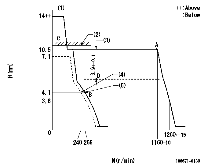
N:Pump speed
R:Rack position (mm)
(1)Target notch: K
(2)Boost compensator excessive fuel lever at operation: L1
(3)Boost compensator stroke
(4)Set idle sub-spring
(5)Main spring setting
----------
K=8 L1=10.5+0.2mm
----------
----------
K=8 L1=10.5+0.2mm
----------
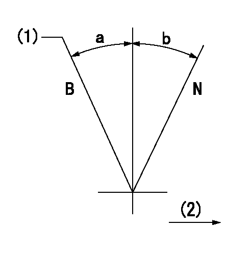
Speed control lever angle

F:Full speed
I:Idle
(1)Stopper bolt setting
----------
----------
a=8deg+-5deg b=31deg+-5deg
----------
----------
a=8deg+-5deg b=31deg+-5deg
Stop lever angle

N:Pump normal
S:Stop the pump.
----------
----------
a=27deg+-5deg b=53deg+-5deg
----------
----------
a=27deg+-5deg b=53deg+-5deg
0000001101
N:Normal
B:When boosted
(1)Rack position = aa
(2)Drive side
----------
aa=R1(10.5)+0.2mm
----------
a=(15deg) b=(15deg)
----------
aa=R1(10.5)+0.2mm
----------
a=(15deg) b=(15deg)
Timing setting

(1)Pump vertical direction
(2)Coupling's key groove position at No 1 cylinder's beginning of injection
(3)-
(4)-
----------
----------
a=(40deg)
----------
----------
a=(40deg)
Information:
Illustration 1 g01339995
Over Temperature Alarm
The Over Temperature alarm monitors the particulate filter temperature and the over temperature alarm produces an alarm if the temperature exceeds a configurable threshold. The operator is informed of an Over Temperature Alarm. The Over-Temperature Warning alarm is set to the "ON" state when the monitored temperature reaches or exceeds the Assert Alarm temperature value as configured by the user through the monitoring system. Pin 59 in the "ON" state will illuminate the optional Over-Temperature LED. Refer Systems Operation Troubleshooting, Testing and Adjusting, KENR6695-00, "Input Components".Through the CAT ET service tool, the users may configure the conditions to reset the Over-Temperature Warning alarm to "OFF" by choosing one of two methods:
The Over-Temperature Warning alarm will automatically be set to the "OFF" state when the monitored temperature drops below the Assert Alarm temperature value.
The Over-Temperature Warning alarm will stay latched in the "ON" state until cleared by the user through Cat ET.Over-Pressure Alarm
The Over-Pressure Alarm monitors the particulate filter pressure and annunciates an alarm if the pressure exeeds a configurable threshold. The operator should be informed of an Over-Pressure Alarm. There are two configurable Over-Pressure Alarm sets of conditions. By programming the two configurable Over-Pressure Alarm sets differently, one may be considered a Warning alarm and the other as a Critical alarm. The Warning alarm will be associated with Pin 60 (the optional Over-Pressure LED) and the Critical alarm will be associated with Pin 61 (the optional System Problem LED).
The Warning alarm is associated with the Over-Pressure LED.
The Critical alarm is associated with the System Problem LED.Refer Systems Operation Troubleshooting, Testing and Adjusting, KENR6695-00, "Input Components"Conditions To Set The Over-Pressure Alarm To The "ON" State
When the pressure exceeds the Pressure Threshold for the programmed percent of time (Duty Cycle) over the Time Interval, then the appropriate alarm (Over-Pressure or System Problem) is set to "ON". The pressure is sampled in 1 second intervals.Conditions To Set The Over-Pressure Alarm To The "OFF" State
The user may configure the conditions to reset the Over-Pressure alarms to "OFF" by choosing one of two methods:
The Over-Pressure alarm is set to the "OFF" state when the "ON" conditions are no longer met.
The Over-Pressure alarm will stay latched in the "ON" state until the Logged Event is cleared by the user through Cat ET.Configurable Parameters - The following parameters are configurable through the CAT ET service tool,
Particulate Trap Over-Pressure Warning Activation Time Percentage – Default is 10%
Particulate Trap Over-Pressure Warning Alarm Reset Configuration – Default is Manual
Particulate Trap Over-Pressure Critical Alarm Activation Time Percentage – Default is 10%Programmable Monitoring System
The purpose of the programmable monitoring system is to give the customers the ability to customize how the system reacts to possible engine damaging conditions. This feature reduces the number of custom personality modules, and part numbers, needed to meet widely varying customer needs. CAT ET can be used to view Programmable Monitoring System settings and customize the Programmable Monitoring System if allowed via security settings. Table 1 describes the programmable monitoring system. In