Information injection-pump assembly
BOSCH
9 400 616 974
9400616974
ZEXEL
106671-8100
1066718100
HINO
220005980A
220005980a
Rating:
Service parts 106671-8100 INJECTION-PUMP ASSEMBLY:
1.
_
7.
COUPLING PLATE
8.
_
9.
_
11.
Nozzle and Holder
23600-1221C
12.
Open Pre:MPa(Kqf/cm2)
21.6{220}

15.
NOZZLE SET
Include in #1:
106671-8100
as INJECTION-PUMP ASSEMBLY
Cross reference number
BOSCH
9 400 616 974
9400616974
ZEXEL
106671-8100
1066718100
HINO
220005980A
220005980a
Zexel num
Bosch num
Firm num
Name
Calibration Data:
Adjustment conditions
Test oil
1404 Test oil ISO4113 or {SEAJ967d}
1404 Test oil ISO4113 or {SEAJ967d}
Test oil temperature
degC
40
40
45
Nozzle and nozzle holder
105780-8140
Bosch type code
EF8511/9A
Nozzle
105780-0000
Bosch type code
DN12SD12T
Nozzle holder
105780-2080
Bosch type code
EF8511/9
Opening pressure
MPa
17.2
Opening pressure
kgf/cm2
175
Injection pipe
Outer diameter - inner diameter - length (mm) mm 8-3-600
Outer diameter - inner diameter - length (mm) mm 8-3-600
Overflow valve
134424-0920
Overflow valve opening pressure
kPa
162
147
177
Overflow valve opening pressure
kgf/cm2
1.65
1.5
1.8
Tester oil delivery pressure
kPa
157
157
157
Tester oil delivery pressure
kgf/cm2
1.6
1.6
1.6
Direction of rotation (viewed from drive side)
Left L
Left L
Injection timing adjustment
Direction of rotation (viewed from drive side)
Left L
Left L
Injection order
1-4-2-6-
3-5
Pre-stroke
mm
3.3
3.24
3.3
Beginning of injection position
Drive side NO.1
Drive side NO.1
Difference between angles 1
Cal 1-4 deg. 60 59.75 60.25
Cal 1-4 deg. 60 59.75 60.25
Difference between angles 2
Cyl.1-2 deg. 120 119.75 120.25
Cyl.1-2 deg. 120 119.75 120.25
Difference between angles 3
Cal 1-6 deg. 180 179.75 180.25
Cal 1-6 deg. 180 179.75 180.25
Difference between angles 4
Cal 1-3 deg. 240 239.75 240.25
Cal 1-3 deg. 240 239.75 240.25
Difference between angles 5
Cal 1-5 deg. 300 299.75 300.25
Cal 1-5 deg. 300 299.75 300.25
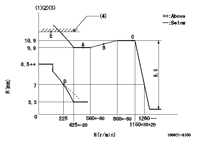
Injection quantity adjustment
Adjusting point
A
Rack position
9.9
Pump speed
r/min
500
500
500
Average injection quantity
mm3/st.
125.5
122.5
128.5
Max. variation between cylinders
%
0
-4
4
Fixing the lever
*
Injection quantity adjustment_02
Adjusting point
B
Rack position
10.5
Pump speed
r/min
700
700
700
Average injection quantity
mm3/st.
141.2
139.2
143.2
Max. variation between cylinders
%
0
-2
2
Basic
*
Fixing the lever
*
Injection quantity adjustment_03
Adjusting point
C
Rack position
10.9
Pump speed
r/min
1150
1150
1150
Average injection quantity
mm3/st.
149.7
146.7
152.7
Max. variation between cylinders
%
0
-4
4
Fixing the lever
*
Injection quantity adjustment_04
Adjusting point
D
Rack position
7+-0.5
Pump speed
r/min
225
225
225
Average injection quantity
mm3/st.
16
13
19
Max. variation between cylinders
%
0
-15
15
Fixing the rack
*
Injection quantity adjustment_05
Adjusting point
E
Rack position
-
Pump speed
r/min
100
100
100
Average injection quantity
mm3/st.
135
135
155
Fixing the lever
*
Rack limit
*
Timer adjustment
Pump speed
r/min
950
Advance angle
deg.
0.5
Timer adjustment_02
Pump speed
r/min
1000
Advance angle
deg.
1.5
Timer adjustment_03
Pump speed
r/min
1050
Advance angle
deg.
1.9
1.4
2.4
Timer adjustment_04
Pump speed
r/min
1150
Advance angle
deg.
4.5
4.2
4.8
Remarks
Finish
Finish
Test data Ex:
Governor adjustment
N:Pump speed
R:Rack position (mm)
(1)Lever ratio: RT
(2)Target shim dimension: TH
(3)Damper spring setting: DL
(4)RACK LIMIT
----------
RT=1 TH=1.8mm DL=6.2-0.2mm
----------
----------
RT=1 TH=1.8mm DL=6.2-0.2mm
----------
Speed control lever angle

F:Full speed
----------
----------
a=15deg+-5deg
----------
----------
a=15deg+-5deg
0000000901

F:Full load
I:Idle
(1)Stopper bolt setting
----------
----------
a=10deg+-5deg b=25deg+-3deg
----------
----------
a=10deg+-5deg b=25deg+-3deg
Stop lever angle

N:Pump normal
S:Stop the pump.
----------
----------
a=15deg+-5deg b=64deg+-5deg
----------
----------
a=15deg+-5deg b=64deg+-5deg
Timing setting

(1)Pump vertical direction
(2)Coupling's key groove position at No 1 cylinder's beginning of injection
(3)-
(4)-
----------
----------
a=(0deg)
----------
----------
a=(0deg)
Information:
Illustration 1 g00280782
Connections for the Electronic Technician (ET)The components that are needed in order to use the CAT Electronic Technician in order to determine diagnostic codes are listed: (1) An IBM-COMPATIBLE personal computer with an installed current version of Caterpillar Electronic Technician software (2) 139-4166 Data Link Cable or 7X-1570 Data Link Cable (3) 7X-1425 Cable and 4C-6805 Adapter (4) Special Publication, JEBD3003, Special Publication, JERD2124, Special Publication, JERD2129 ; Caterpillar Electronic Technician software (5) 7X-1700 Communication Adapter Tool with Special Publication, NEXG4323, "Communications Adapter Software"
Illustration 2 g00774942
Connections for the Communication Adapter II and the Electronic Technician (ET)The components that are needed in order to use the Communication Adapter II and the CAT Electronic Technician in order to determine diagnostic codes are listed: (6) Cable (7) 171-4400 Communication Adapter ii (8) Service diagnostic cable. (9) Current version of Caterpillar Electronic Technician software and an IBM-COMPATIBLE personal computerReferenceSee Special Publication, NEHS0758, "Communications Adapter II User's Manual Contains Software".Note: Caterpillar Electronic Technician (ET) is a software program that can be used on an IBM compatible personal computer. In order to use the Caterpillar Electronic Technician (ET), order the following materials: Special Publication, JERD2124, "ET Single Use Program License", Special Publication, JEHP1026, "Information and Requirements Sheet", 7X-1425 Data Link Cable and the Data Subscription and Special Publication, JERD2142, "Data Subscription". The Special Publication, JEHP1026, "Information and Requirements Sheet" lists the required hardware and the features of the ET.The Electronic Technician (ET) is not required in order to determine the diagnostic codes and the ET is not required in order to clear the diagnostic codes. However, the process of determining the diagnostic codes is easier and faster by using the ET. The ET can also display information on the history of a diagnostic code and the parameter status of diagnostic codes. These features allow the ET to be a useful tool for troubleshooting.The Electronic Technician (ET) is used to communicate to the electronic control module over the data link by connecting to the machine diagnostic connector. The diagnostic connector is located by the circuit breaker panel. For more information and the locations of the connectors, see Troubleshooting, "Electrical Components and Connector Locations" and the Electrical System Schematic in your machine's Service Manual.Connect the ET to the machine. Turn the key start switch to the RUN position. Start the ET. The ET will initiate communications with the electronic control modules on the machine. The ET will list the available electronic control modules on the machine after communication has been established.