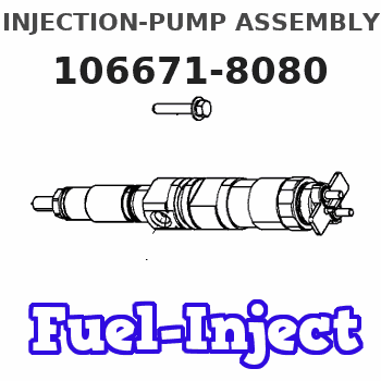
Information injection-pump assembly
BOSCH
9 400 619 662
9400619662
ZEXEL
106671-8080
1066718080
Rating:
Cross reference number
BOSCH
9 400 619 662
9400619662
ZEXEL
106671-8080
1066718080
Zexel num
Bosch num
Firm num
Name
Calibration Data:
Adjustment conditions
Test oil
1404 Test oil ISO4113 or {SAEJ967d}
1404 Test oil ISO4113 or {SAEJ967d}
Test oil temperature
degC
40
40
45
Nozzle and nozzle holder
105780-8140
Bosch type code
EF8511/9A
Nozzle
105780-0000
Bosch type code
DN12SD12T
Nozzle holder
105780-2080
Bosch type code
EF8511/9
Opening pressure
MPa
17.2
Opening pressure
kgf/cm2
175
Injection pipe
Outer diameter - inner diameter - length (mm) mm 8-3-600
Outer diameter - inner diameter - length (mm) mm 8-3-600
Overflow valve
134424-1420
Overflow valve opening pressure
kPa
162
147
177
Overflow valve opening pressure
kgf/cm2
1.65
1.5
1.8
Tester oil delivery pressure
kPa
157
157
157
Tester oil delivery pressure
kgf/cm2
1.6
1.6
1.6
Direction of rotation (viewed from drive side)
Right R
Right R
Injection timing adjustment
Direction of rotation (viewed from drive side)
Right R
Right R
Injection order
1-4-2-6-
3-5
Pre-stroke
mm
4.5
4.4
4.5
Beginning of injection position
Drive side NO.1
Drive side NO.1
Difference between angles 1
Cal 1-4 deg. 60 59.5 60.5
Cal 1-4 deg. 60 59.5 60.5
Difference between angles 2
Cyl.1-2 deg. 120 119.5 120.5
Cyl.1-2 deg. 120 119.5 120.5
Difference between angles 3
Cal 1-6 deg. 180 179.5 180.5
Cal 1-6 deg. 180 179.5 180.5
Difference between angles 4
Cal 1-3 deg. 240 239.5 240.5
Cal 1-3 deg. 240 239.5 240.5
Difference between angles 5
Cal 1-5 deg. 300 299.5 300.5
Cal 1-5 deg. 300 299.5 300.5
Injection quantity adjustment
Adjusting point
A
Rack position
8
Pump speed
r/min
800
800
800
Average injection quantity
mm3/st.
118.5
116.5
120.5
Max. variation between cylinders
%
0
-2
2
Basic
*
Fixing the lever
*
Injection quantity adjustment_02
Adjusting point
B
Rack position
5+-0.5
Pump speed
r/min
400
400
400
Average injection quantity
mm3/st.
10.2
7.2
13.2
Max. variation between cylinders
%
0
-15
15
Fixing the rack
*
Injection quantity adjustment_03
Adjusting point
C
Rack position
-
Pump speed
r/min
100
100
100
Average injection quantity
mm3/st.
134
129
139
Fixing the lever
*
Rack limit
*
Timer adjustment
Pump speed
r/min
975--
Advance angle
deg.
0
0
0
Remarks
Start
Start
Timer adjustment_02
Pump speed
r/min
925
Advance angle
deg.
0.3
Timer adjustment_03
Pump speed
r/min
1000
Advance angle
deg.
0.8
0.3
1.3
Timer adjustment_04
Pump speed
r/min
-
Advance angle
deg.
2.5
2.5
2.5
Remarks
Measure the actual speed, stop
Measure the actual speed, stop
Test data Ex:
Governor adjustment
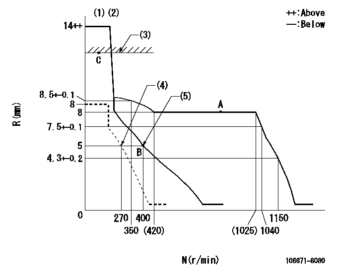
N:Pump speed
R:Rack position (mm)
(1)Target notch: K
(2)Tolerance for racks not indicated: +-0.05mm.
(3)RACK LIMIT
(4)Set idle sub-spring
(5)Main spring setting
----------
K=13
----------
----------
K=13
----------
Speed control lever angle

F:Full speed
I:Idle
S:Stop
----------
----------
a=7deg+-5deg b=32deg+-3deg c=16deg+-5deg
----------
----------
a=7deg+-5deg b=32deg+-3deg c=16deg+-5deg
Stop lever angle

N:Pump normal
S:Stop the pump.
(1)Normal
(2)Rack position aa or less, pump speed bb
----------
aa=4.5mm bb=0r/min
----------
a=27deg+-5deg b=53deg+-5deg
----------
aa=4.5mm bb=0r/min
----------
a=27deg+-5deg b=53deg+-5deg
0000001501 LEVER
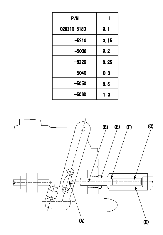
(F) P/N: Part number of the shim
L1:Thickness (mm)
1. Adjustment of the control lever
(1)Perform idling with the control lever (A) contacting the pushrod (B). At this time, confirm that the spring (C) is not compressed by control lever (A)'s operating torque.
(2)To set the stop position, compress spring (C) using the control lever (A) and adjust the rack so that it contacts the guide screw (D) at position L2. Then, set and fix using the lock nut (E). Adjust the rack position L2 at this time using the shim (F).
(3)Confirm that the control lever (A) returns to the idling position when pulled in the stop direction and then released.
----------
L2=0.2~2mm
----------
----------
L2=0.2~2mm
----------
Timing setting

(1)Pump vertical direction
(2)Coupling's key groove position at No 1 cylinder's beginning of injection
(3)-
(4)-
----------
----------
a=(40deg)
----------
----------
a=(40deg)
Information:
Cat Diesel Fuel Conditioner
Note: Cat Diesel Fuel Conditioner, part number 256-4968, is the only fuel conditioner/additive available to the end user that is tested and approved by Caterpillar for use in Caterpillar diesel engines.Cat Diesel Fuel Conditioner is a proprietary metal and ash free formulation that has been extensively tested for use with distillate diesel fuels for use in Caterpillar diesel engines. Cat Diesel Fuel Conditioner helps address many of the challenges that various fuels worldwide present in regards to fuel life/stability, engine startability, injector deposits, fuel system life, and long term engine performance.Note: Diesel fuel additives/conditioners may not improve markedly poor diesel fuel properties enough to make them acceptable for use.Note: For maximum overall benefits, ask your fuel supplier to add Cat Diesel Fuel Conditioner at the recommended treat rate before fuel delivery, or you may add Cat Diesel Fuel Conditioner at the recommended treat rate during the early weeks of fuel storage. Follow all applicable national, regional, and local laws, mandates, and regulations concerning the use of diesel fuel conditioners/additives.Cat Diesel Fuel Conditioner is a proven high performance, multipurpose diesel fuel conditioner that is designed to improve:
Fuel economy (through fuel system cleanup)
Lubricity
Oxidative stability
Detergency/dispersancy
Moisture dispersancy
Corrosion protection
Cetane (typically 2-3 cetane numbers)Cat Diesel Fuel Conditioner has been validated through lab and field tests to improve/reduce diesel fuel consumption and emissions for typical fleets through fuel system/injector cleanup, and to help maintain new engine performance by keeping fuel systems clean. Note that while fuel system/injector cleanup takes place over time, maintaining fuel system/injector cleanliness is an ongoing process.Data indicates that average fuel economy improvements across typical fleets may be in the 2-3+ percentage range. Note that improvements may vary based on factors such as engine model, age and condition of the engine, and application.Cat Diesel Fuel Conditioner also reduces the formation of gums, resins, and sludge, and disperses insoluble gums. This can dramatically improve fuel storage life, reduce fuel related engine deposits and corrosion, and extend fuel filter life.Note: Use of Cat Diesel Fuel Conditioner does not lessen the engine owner and/or fuel supplier responsibility to follow all industry standard maintenance practices for fuel storage and for fuel handling. Refer to the "General Fuel Information" article in this Special Publication for additional information. Additionally, use of Cat Diesel Fuel Conditioner does NOT lessen the engine owner responsibility to use appropriate diesel fuel. Refer to the "Fuel Specifications" section in this Special Publication (Maintenance Section) for guidance.Cat Diesel Fuel Conditioner is suitable for use with biodiesel/biodiesel blends that meet Caterpillar biodiesel recommendations and requirements. Note that not all fuel additives are suitable for use with biodiesel/biodiesel blends. Read and follow all applicable label usage instructions. Also, refer to this Special Publication, "Distillate Diesel Fuel" article, which includes Caterpillar biodiesel recommendations and requirements. Caterpillar strongly recommends the use of Cat Diesel Fuel Conditioner with biodiesel and biodiesel blends.When used as directed, Cat Diesel Fuel Conditioner has proven to be compatible with existing and U.S. EPA 2007 on-highway certified diesel engine emission control