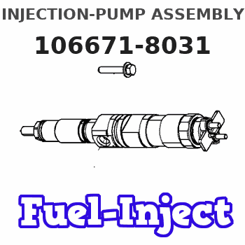
Information injection-pump assembly
BOSCH
9 400 616 968
9400616968
ZEXEL
106671-8031
1066718031
HINO
220005600B
220005600b
Rating:
Cross reference number
BOSCH
9 400 616 968
9400616968
ZEXEL
106671-8031
1066718031
HINO
220005600B
220005600b
Zexel num
Bosch num
Firm num
Name
106671-8031
9 400 616 968
220005600B HINO
INJECTION-PUMP ASSEMBLY
EK200 * K 14CA PE6P,6PD PE
EK200 * K 14CA PE6P,6PD PE
Calibration Data:
Adjustment conditions
Test oil
1404 Test oil ISO4113 or {SAEJ967d}
1404 Test oil ISO4113 or {SAEJ967d}
Test oil temperature
degC
40
40
45
Nozzle and nozzle holder
105780-8140
Bosch type code
EF8511/9A
Nozzle
105780-0000
Bosch type code
DN12SD12T
Nozzle holder
105780-2080
Bosch type code
EF8511/9
Opening pressure
MPa
17.2
Opening pressure
kgf/cm2
175
Injection pipe
Outer diameter - inner diameter - length (mm) mm 8-3-600
Outer diameter - inner diameter - length (mm) mm 8-3-600
Overflow valve
134424-0920
Overflow valve opening pressure
kPa
162
147
177
Overflow valve opening pressure
kgf/cm2
1.65
1.5
1.8
Tester oil delivery pressure
kPa
157
157
157
Tester oil delivery pressure
kgf/cm2
1.6
1.6
1.6
Direction of rotation (viewed from drive side)
Left L
Left L
Injection timing adjustment
Direction of rotation (viewed from drive side)
Left L
Left L
Injection order
1-4-2-6-
3-5
Pre-stroke
mm
4.8
4.74
4.8
Beginning of injection position
Drive side NO.1
Drive side NO.1
Difference between angles 1
Cal 1-4 deg. 60 59.75 60.25
Cal 1-4 deg. 60 59.75 60.25
Difference between angles 2
Cyl.1-2 deg. 120 119.75 120.25
Cyl.1-2 deg. 120 119.75 120.25
Difference between angles 3
Cal 1-6 deg. 180 179.75 180.25
Cal 1-6 deg. 180 179.75 180.25
Difference between angles 4
Cal 1-3 deg. 240 239.75 240.25
Cal 1-3 deg. 240 239.75 240.25
Difference between angles 5
Cal 1-5 deg. 300 299.75 300.25
Cal 1-5 deg. 300 299.75 300.25
Injection quantity adjustment
Adjusting point
A
Rack position
7.9
Pump speed
r/min
500
500
500
Average injection quantity
mm3/st.
153
150
156
Max. variation between cylinders
%
0
-4
4
Fixing the lever
*
Injection quantity adjustment_02
Adjusting point
B
Rack position
7.9
Pump speed
r/min
700
700
700
Average injection quantity
mm3/st.
151
149
153
Max. variation between cylinders
%
0
-2
2
Basic
*
Fixing the lever
*
Injection quantity adjustment_03
Adjusting point
C
Rack position
8.3
Pump speed
r/min
1075
1075
1075
Average injection quantity
mm3/st.
159
156
162
Max. variation between cylinders
%
0
-4
4
Fixing the lever
*
Injection quantity adjustment_04
Adjusting point
D
Rack position
4+-0.5
Pump speed
r/min
225
225
225
Average injection quantity
mm3/st.
13
10
16
Max. variation between cylinders
%
0
-15
15
Fixing the rack
*
Injection quantity adjustment_05
Adjusting point
E
Rack position
8.6+-0.5
Pump speed
r/min
100
100
100
Average injection quantity
mm3/st.
140
140
150
Fixing the lever
*
Rack limit
*
Injection quantity adjustment_06
Adjusting point
F
Rack position
7.2
Pump speed
r/min
1150
1150
1150
Average injection quantity
mm3/st.
134.7
129.7
139.7
Fixing the lever
*
Timer adjustment
Pump speed
r/min
865+50
Advance angle
deg.
0
0
0
Remarks
Start
Start
Timer adjustment_02
Pump speed
r/min
1075
Advance angle
deg.
4.5
4.2
4.8
Remarks
Finish
Finish
Test data Ex:
Governor adjustment
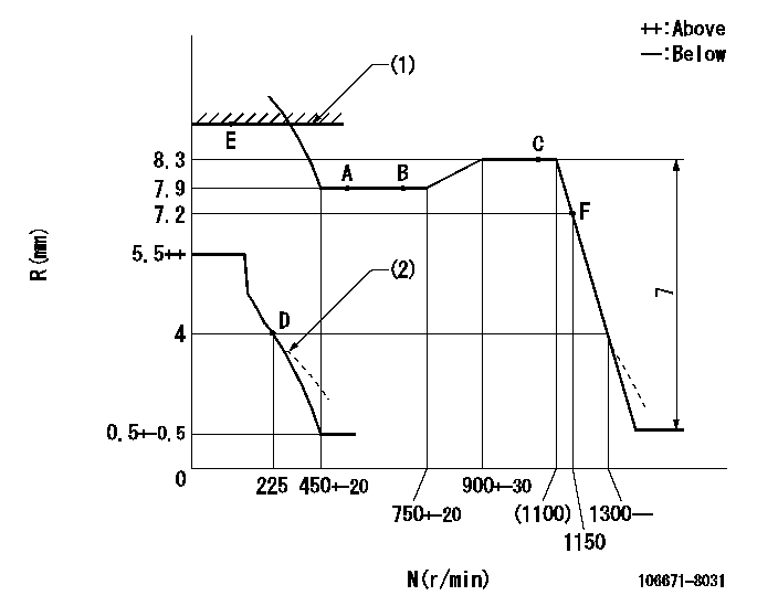
N:Pump speed
R:Rack position (mm)
(1)RACK LIMIT: RAL
(2)Damper spring setting: DL
----------
RAL=(8.6)mm DL=3.3-0.2mm
----------
----------
RAL=(8.6)mm DL=3.3-0.2mm
----------
Speed control lever angle

F:Full speed
----------
----------
a=17deg+-5deg
----------
----------
a=17deg+-5deg
0000000901
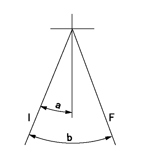
F:Full load
I:Idle
----------
----------
a=17deg+-5deg b=39deg+-3deg
----------
----------
a=17deg+-5deg b=39deg+-3deg
Stop lever angle

N:Pump normal
S:Stop the pump.
----------
----------
a=40deg+-5deg b=64deg+-5deg
----------
----------
a=40deg+-5deg b=64deg+-5deg
0000001501 MICRO SWITCH
Switch adjustment
Adjust the bolt so that the lower lever position is obtained when the switch is turned ON.
(1)Speed N1
(2)Rack position Ra
----------
N1=300+25r/min Ra=4mm
----------
----------
N1=300+25r/min Ra=4mm
----------
Timing setting

(1)Pump vertical direction
(2)Coupling's key groove position at No 1 cylinder's beginning of injection
(3)-
(4)-
----------
----------
a=(0deg)
----------
----------
a=(0deg)
Information:
Introduction
Do not perform any procedure in this Special Instruction until you have read the information and you understand the information.If the crankshaft, gear case and/or crank gear are replaced, it is necessary to perform the injection timing correction procedure. The following steps show how to calculate/determine the new injection timing by measuring angular deviation between the crankshaft TDC and Crank Position sensor detected TDC.Note: Once complete the engine ecm must be reprogrammed with the new injection timing value. Follow all Steps below.Procedure
Illustration 1 g06220080
(1) TC Mark (Flywheel Housing)
(2) TC Mark (Flywheel)
Remove valve cover, injector, and rocker arm. Bring the piston of cylinder 4 to TDC.
Illustration 2 g06220082
(3) Dial Gauge
(4) Valve
(5) O-ring
Remove the #4 exhaust valve bridge arm and valve spring. Insert a small O-ring (5) so the valve (4) does not fall into the cylinder.
Set the dial gauge (3) on the tip of the valve (4).
Illustration 3 g06220083
(6) Tri-sqaure
(7) Flywheel Housing
(8) Flywheel
Illustration 4 g06220087
(7) Flywheel Housing
(8) Flywheel
(9) Reference Line
Turn the flywheel counterclockwise and measure the position where the tip of the valve is highest.
Stop the flywheel at the position where the tip of the valve is the highest. Put a tri-sqaure (6) on the flywheel housing (7) and the flywheel (8) and draw a reference line (9).Do not drop the valve (4) into the cylinder. When measuring the highest position of the tip of the valve do not rotate the flywheel clockwise. If you go past the highest point of the valve, back up the flywheel slightly and measure the highest point of the valve. The reference line (9) indicates the TDC of the crankshaft.
Illustration 5 g06220092
(10) Tester
(11) Crankshaft Position Sensor
Illustration 6 g06220095
(11) Crankshaft Position Sensor
(12) Ground Terminal
(13) Output Terminal
Connect the engine harness and the main switch. Connect battery.Attach the tester (10) to the output terminal (13) and the ground terminal (12) of the crankshaft position sensor (11). Turn the main switch "ON". Turn the flywheel and make sure that the voltage of the crankshaft position sensor goes from 0→ 5 V or 5 → 0 V.
Illustration 7 g06220100
(14) Pulsar Gear
(15) 14th Tooth
(16) Missing Teeth
Rotate the flywheel and align the crankshaft position sensor to the part of the pulsar gear (14) that is missing teeth (16). The 14th tooth (15) from the missing teeth is the standard. Slowly turn the flywheel counterclockwise and stop the flywheel at the point where the needle of the tester changes momentarily from 0→ 5 V, the 14th tooth. That point is where the crankshaft position sensor detects TDC.
Illustration 8 g06220101
(17) Crankshaft TDC
(18) Detection Point of Crankshaft Position Sensor TDC
Illustration 9 g06220104
(19) Interval
Set the tri-square (6) on the reference line (9) on the flywheel housing side and mark the detection point of the crankshaft position sensor TDC (18) on the flywheel.
Measure the interval (19) between the crankshaft TDC (17) and the detection point of the crankshaft position sensor TDC (18).
Calculation of the fuel injection timing correction 1 mm (0.039 inch): 0.342°.Corrected angle = 0.342° X actual interval.
Overwrite the injection timing correction value on the engine ecm registration website refer to REHS9707, "Registering
Have questions with 106671-8031?
Group cross 106671-8031 ZEXEL
Hino
106671-8031
9 400 616 968
220005600B
INJECTION-PUMP ASSEMBLY
EK200
EK200