Information injection-pump assembly
BOSCH
9 400 616 960
9400616960
ZEXEL
106671-7900
1066717900
MITSUBISHI
ME050867
me050867
Rating:
Service parts 106671-7900 INJECTION-PUMP ASSEMBLY:
1.
_
7.
COUPLING PLATE
8.
_
9.
_
11.
Nozzle and Holder
ME059740
12.
Open Pre:MPa(Kqf/cm2)
21.6(220)
15.
NOZZLE SET
Include in #1:
106671-7900
as INJECTION-PUMP ASSEMBLY
Cross reference number
BOSCH
9 400 616 960
9400616960
ZEXEL
106671-7900
1066717900
MITSUBISHI
ME050867
me050867
Zexel num
Bosch num
Firm num
Name
106671-7900
9 400 616 960
ME050867 MITSUBISHI
INJECTION-PUMP ASSEMBLY
6D22TC * K
6D22TC * K
Calibration Data:
Adjustment conditions
Test oil
1404 Test oil ISO4113 or {SAEJ967d}
1404 Test oil ISO4113 or {SAEJ967d}
Test oil temperature
degC
40
40
45
Nozzle and nozzle holder
105780-8140
Bosch type code
EF8511/9A
Nozzle
105780-0000
Bosch type code
DN12SD12T
Nozzle holder
105780-2080
Bosch type code
EF8511/9
Opening pressure
MPa
17.2
Opening pressure
kgf/cm2
175
Injection pipe
Outer diameter - inner diameter - length (mm) mm 8-3-600
Outer diameter - inner diameter - length (mm) mm 8-3-600
Overflow valve
131424-4620
Overflow valve opening pressure
kPa
255
221
289
Overflow valve opening pressure
kgf/cm2
2.6
2.25
2.95
Tester oil delivery pressure
kPa
157
157
157
Tester oil delivery pressure
kgf/cm2
1.6
1.6
1.6
Direction of rotation (viewed from drive side)
Right R
Right R
Injection timing adjustment
Direction of rotation (viewed from drive side)
Right R
Right R
Injection order
1-5-3-6-
2-4
Pre-stroke
mm
4.8
4.75
4.85
Beginning of injection position
Governor side NO.1
Governor side NO.1
Difference between angles 1
Cal 1-5 deg. 60 59.5 60.5
Cal 1-5 deg. 60 59.5 60.5
Difference between angles 2
Cal 1-3 deg. 120 119.5 120.5
Cal 1-3 deg. 120 119.5 120.5
Difference between angles 3
Cal 1-6 deg. 180 179.5 180.5
Cal 1-6 deg. 180 179.5 180.5
Difference between angles 4
Cyl.1-2 deg. 240 239.5 240.5
Cyl.1-2 deg. 240 239.5 240.5
Difference between angles 5
Cal 1-4 deg. 300 299.5 300.5
Cal 1-4 deg. 300 299.5 300.5
Injection quantity adjustment
Adjusting point
A
Rack position
11.4
Pump speed
r/min
750
750
750
Average injection quantity
mm3/st.
154.7
151.7
157.7
Max. variation between cylinders
%
0
-3
3
Basic
*
Fixing the lever
*
Injection quantity adjustment_02
Adjusting point
B
Rack position
10.8
Pump speed
r/min
750
750
750
Average injection quantity
mm3/st.
137.9
134.9
140.9
Fixing the lever
*
Injection quantity adjustment_03
Adjusting point
C
Rack position
6.3+-0.5
Pump speed
r/min
300
300
300
Average injection quantity
mm3/st.
11.2
8.6
13.8
Fixing the rack
*
Remarks
(check)
(check)
Injection quantity adjustment_04
Adjusting point
D
Rack position
5.5+-0.5
Pump speed
r/min
500
500
500
Average injection quantity
mm3/st.
10.2
7.6
12.8
Max. variation between cylinders
%
0
-15
15
Fixing the rack
*
Timer adjustment
Pump speed
r/min
900++
Advance angle
deg.
0
0
0
Remarks
Do not advance until starting N = 900.
Do not advance until starting N = 900.
Timer adjustment_02
Pump speed
r/min
900
Advance angle
deg.
0.5
Timer adjustment_03
Pump speed
r/min
-
Advance angle
deg.
1.5
1.5
1.5
Remarks
Measure the actual speed, stop
Measure the actual speed, stop
Test data Ex:
Governor adjustment
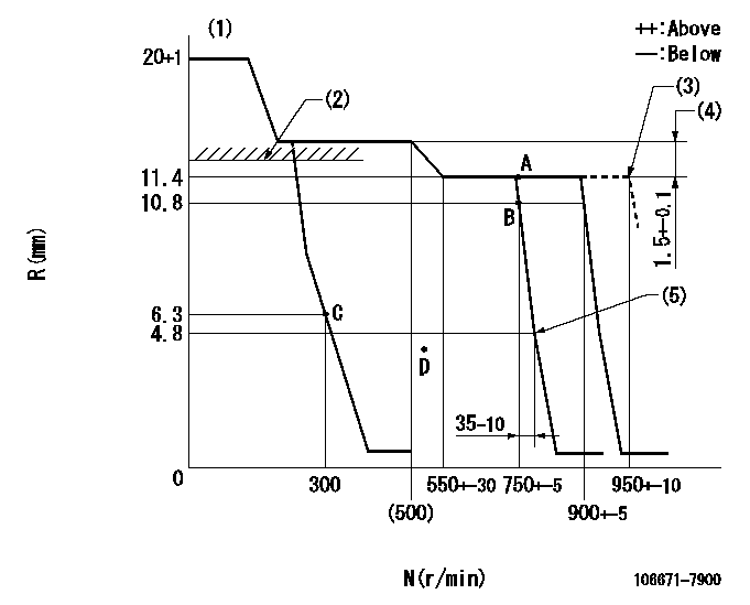
N:Pump speed
R:Rack position (mm)
(1)Target notch: K
(2)RACK LIMIT: RAL
(3)At shipping
(4)Rack difference between N = N1 and N = N2
(5)Idle sub spring setting: L1.
----------
K=6 RAL=11.7+0.2mm N1=750r/min N2=450r/min L1=4.3+-0.1mm
----------
----------
K=6 RAL=11.7+0.2mm N1=750r/min N2=450r/min L1=4.3+-0.1mm
----------
Speed control lever angle
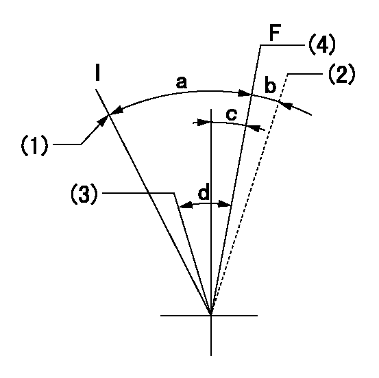
F:Full speed
I:Idle
(1)Stopper bolt setting
(2)At shipping
(3)Pump speed = aa
(4)Pump speed = bb
----------
aa=750r/min bb=900r/min
----------
a=(25deg)+-5deg b=(2deg) c=(0deg)+-5deg d=(7deg)+-5deg
----------
aa=750r/min bb=900r/min
----------
a=(25deg)+-5deg b=(2deg) c=(0deg)+-5deg d=(7deg)+-5deg
Stop lever angle
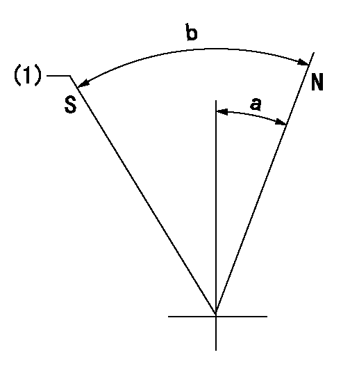
N:Pump normal
S:Stop the pump.
(1)At shipping
----------
----------
a=39deg+-5deg b=53deg+-5deg
----------
----------
a=39deg+-5deg b=53deg+-5deg
Timing setting

(1)Pump vertical direction
(2)Coupling's key groove position at No 1 cylinder's beginning of injection
(3)-
(4)-
----------
----------
a=(7deg)
----------
----------
a=(7deg)
Information:
Introduction
Do not perform any procedure in this Special Instruction until you read this information and you understand this information.This Special Instruction provides the following information for 3600 Diesel Engines:
Identification of a service tool
A procedure to check cylinder pressureService Tool
Illustration 1 g01250874
4C-6585 Indicator Group (1) Hand tool for tightening gauge connectionProcedure for Checking Cylinder Pressure
Take the readings for cylinder pressure at the rated speed and at the rated load in order to obtain the peak cylinder pressure for a specific rating.Readings for cylinder pressure can also be taken at a light load condition or at a no-load condition. These pressure readings can be used as a baseline for a comparison at a later date. For a valid comparison, pressure measurements that are taken at a later date must duplicate the initial load conditions.
Illustration 2 g01250892
(2) Cylinder pressure valve (Kiene valve) (3) Valve stem (4) Cap
Remove cap (4) from valve (2) .
Fluids may escape from the cylinder pressure valves at high velocity during this procedure and cause personal injury. Always stay clear and keep personnel away from the cylinder pressure valves during this procedure.
Stand to the side of the valve and open valve stem (3) approximately 90° (1/4 turn) counterclockwise. Close valve stem (3). This will blow any foreign debris out of the valve.
Illustration 3 g01250917
(5) 4C-9736 Pressure Gauge (6) 4C-9737 Gauge connection
Install the 4C-6585 Indicator group on the valve. Use tool (1) that is provided in the indicator group in order to tighten gauge connection (6) to a torque of 17 3 N m (12 2 lb ft). Do not overtighten the gauge connection.
Open valve stem (3) by approximately 540° (1 1/2 turn) counterclockwise. Document the reading on pressure gauge (5) and close valve stem (3). Tighten the valve stem to a torque of 24 3 N m (18 2 lb ft). Do not overtighten the valve stem.
Use the hand tool that is provided in the indicator group in order to loosen the gauge connection. Remove the 4C-6585 Indicator Group .
Install cap (4). Tighten to a torque of 17 3 N m (12 2 lb ft). Do not overtighten the cap.
Have questions with 106671-7900?
Group cross 106671-7900 ZEXEL
Mitsubishi
106671-7900
9 400 616 960
ME050867
INJECTION-PUMP ASSEMBLY
6D22TC
6D22TC