Information injection-pump assembly
ZEXEL
106671-7600
1066717600
Rating:
Cross reference number
ZEXEL
106671-7600
1066717600
Zexel num
Bosch num
Firm num
Name
Calibration Data:
Adjustment conditions
Test oil
1404 Test oil ISO4113 or {SAEJ967d}
1404 Test oil ISO4113 or {SAEJ967d}
Test oil temperature
degC
40
40
45
Nozzle and nozzle holder
105780-8140
Bosch type code
EF8511/9A
Nozzle
105780-0000
Bosch type code
DN12SD12T
Nozzle holder
105780-2080
Bosch type code
EF8511/9
Opening pressure
MPa
17.2
Opening pressure
kgf/cm2
175
Injection pipe
Outer diameter - inner diameter - length (mm) mm 8-3-600
Outer diameter - inner diameter - length (mm) mm 8-3-600
Overflow valve
131424-4620
Overflow valve opening pressure
kPa
255
221
289
Overflow valve opening pressure
kgf/cm2
2.6
2.25
2.95
Tester oil delivery pressure
kPa
157
157
157
Tester oil delivery pressure
kgf/cm2
1.6
1.6
1.6
Direction of rotation (viewed from drive side)
Right R
Right R
Injection timing adjustment
Direction of rotation (viewed from drive side)
Right R
Right R
Injection order
1-5-3-6-
2-4
Pre-stroke
mm
4.8
4.75
4.85
Beginning of injection position
Governor side NO.1
Governor side NO.1
Difference between angles 1
Cal 1-5 deg. 60 59.5 60.5
Cal 1-5 deg. 60 59.5 60.5
Difference between angles 2
Cal 1-3 deg. 120 119.5 120.5
Cal 1-3 deg. 120 119.5 120.5
Difference between angles 3
Cal 1-6 deg. 180 179.5 180.5
Cal 1-6 deg. 180 179.5 180.5
Difference between angles 4
Cyl.1-2 deg. 240 239.5 240.5
Cyl.1-2 deg. 240 239.5 240.5
Difference between angles 5
Cal 1-4 deg. 300 299.5 300.5
Cal 1-4 deg. 300 299.5 300.5
Injection quantity adjustment
Adjusting point
-
Rack position
9.4
Pump speed
r/min
700
700
700
Each cylinder's injection qty
mm3/st.
144
140.5
147.5
Basic
*
Fixing the rack
*
Standard for adjustment of the maximum variation between cylinders
*
Injection quantity adjustment_02
Adjusting point
F
Rack position
5+-0.5
Pump speed
r/min
500
500
500
Each cylinder's injection qty
mm3/st.
16.5
14.2
18.8
Fixing the rack
*
Standard for adjustment of the maximum variation between cylinders
*
Injection quantity adjustment_03
Adjusting point
A
Rack position
R1(9.4)
Pump speed
r/min
700
700
700
Average injection quantity
mm3/st.
144
143
145
Basic
*
Fixing the lever
*
Boost pressure
kPa
43.3
43.3
Boost pressure
mmHg
325
325
Injection quantity adjustment_04
Adjusting point
B
Rack position
R1(9.4)
Pump speed
r/min
1100
1100
1100
Average injection quantity
mm3/st.
152.8
149.6
156
Difference in delivery
mm3/st.
6.4
6.4
6.4
Fixing the lever
*
Boost pressure
kPa
43.3
43.3
Boost pressure
mmHg
325
325
Injection quantity adjustment_05
Adjusting point
D
Rack position
9.3
Pump speed
r/min
500
500
500
Average injection quantity
mm3/st.
139.5
135.5
143.5
Fixing the lever
*
Boost pressure
kPa
28
28
28
Boost pressure
mmHg
210
210
210
Injection quantity adjustment_06
Adjusting point
C
Rack position
5.7+-0.5
Pump speed
r/min
225
225
225
Each cylinder's injection qty
mm3/st.
16.5
14
19
Fixing the rack
*
Boost pressure
kPa
0
0
0
Boost pressure
mmHg
0
0
0
Remarks
(check)
(check)
Injection quantity adjustment_07
Adjusting point
E
Rack position
-
Pump speed
r/min
100
100
100
Average injection quantity
mm3/st.
125
105
145
Fixing the lever
*
Boost pressure
kPa
0
0
0
Boost pressure
mmHg
0
0
0
Boost compensator adjustment
Pump speed
r/min
600
600
600
Rack position
7.9
Boost pressure
kPa
3.3
3.3
3.3
Boost pressure
mmHg
25
25
25
Boost compensator adjustment_02
Pump speed
r/min
600
600
600
Rack position
8.55
Boost pressure
kPa
14.7
8
21.4
Boost pressure
mmHg
110
60
160
Boost compensator adjustment_03
Pump speed
r/min
600
600
600
Rack position
9.3
Boost pressure
kPa
28
26.7
29.3
Boost pressure
mmHg
210
200
220
Boost compensator adjustment_04
Pump speed
r/min
600
600
600
Rack position
R1(9.4)
Boost pressure
kPa
30
30
30
Boost pressure
mmHg
225
225
225
Timer adjustment
Pump speed
r/min
450--
Advance angle
deg.
0
0
0
Remarks
Start
Start
Timer adjustment_02
Pump speed
r/min
400
Advance angle
deg.
0.5
Timer adjustment_03
Pump speed
r/min
800
Advance angle
deg.
3
2.5
3.5
Remarks
Finish
Finish
Test data Ex:
Governor adjustment
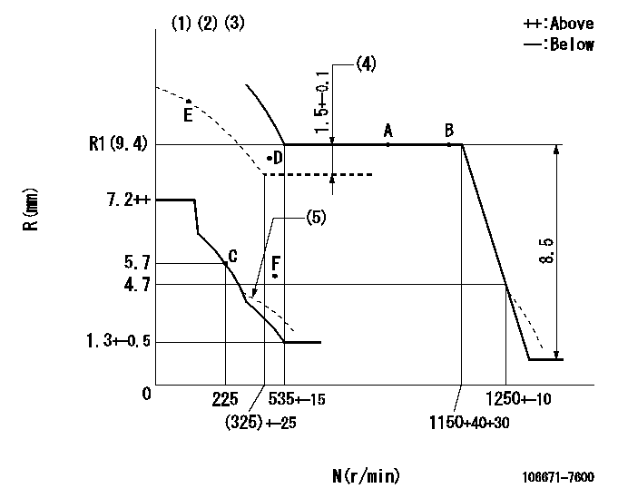
N:Pump speed
R:Rack position (mm)
(1)Lever ratio: RT
(2)Target shim dimension: TH
(3)Boost compensator cancel stroke: BSL
(4)Boost compensator stroke
(5)Damper spring setting: DL
----------
RT=1 TH=1.8mm BSL=2.2mm DL=4.5-0.2mm
----------
----------
RT=1 TH=1.8mm BSL=2.2mm DL=4.5-0.2mm
----------
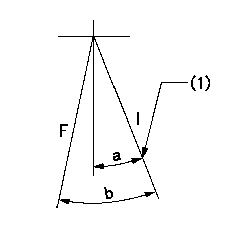
Speed control lever angle

F:Full speed
----------
----------
a=18deg+-5deg
----------
----------
a=18deg+-5deg
0000000901
F:Full load
I:Idle
(1)Stopper bolt setting
----------
----------
a=28deg+-5deg b=30deg+-3deg
----------
----------
a=28deg+-5deg b=30deg+-3deg
Stop lever angle
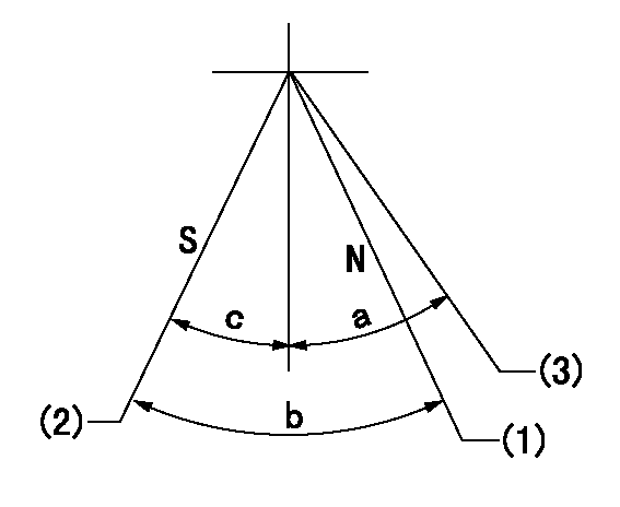
N:Engine manufacturer's normal use
S:Stop the pump.
(1)Rack position = aa
(2)Rack position = bb, set the stopper bolt.
(3)Free (at shipping)
----------
aa=13.3mm bb=4.1-0.5mm
----------
a=(38deg) b=26deg+-5deg c=0deg+7deg-5deg
----------
aa=13.3mm bb=4.1-0.5mm
----------
a=(38deg) b=26deg+-5deg c=0deg+7deg-5deg
0000001501 MICRO SWITCH
Adjustment of the micro-switch
Adjust the bolt to obtain the following lever position when the micro-switch is ON.
(1)Speed N1
(2)Rack position Ra
----------
N1=325+-5r/min Ra=5.4mm
----------
----------
N1=325+-5r/min Ra=5.4mm
----------
Timing setting

(1)Pump vertical direction
(2)Coupling's key groove position at No 1 cylinder's beginning of injection
(3)-
(4)-
----------
----------
a=(7deg)
----------
----------
a=(7deg)
Information:
Introduction
The problem that is identified below does not have a known permanent solution. Until a permanent solution is known, use the solution that is identified below.Problem
There have been instances of event code E930 occurring on certain C7.1 engines. Caterpillar is investigating the root cause of these fault codes and to support the investigation, Caterpillar requests that the following procedure is conducted.Solution
Conduct the following steps and ensure that the "TIB Check List" is completed and submitted to the following email address:venters_phil
Download the "Product Status Report" from the engine ECM.
Record the Clean Emissions Module (CEM) serial number from the data plate on the CEM unit.
Conduct the troubleshooting procedure in Troubleshooting, DEF Pressure Is High.
Download the "Product Status Report" from the engine ECM again.
Conduct an Aftertreatment SCR System Dosing – Test. Refer to Systems Operation, Testing and Adjusting, Aftertreatment SCR System Dosing – Test.Note: When removing the Diesel Exhaust Fluid (DEF) injector from the outlet of the Diesel Particulate Filter (DPF), make sure that photographs of any deposits on the injector tip and within the DEF injector port on the Clean Emissions Module (CEM) are taken and documented.
A photograph of the part number and serial number on the side of the DEF injector and mounting must be taken and documented.
Make sure that the measured amount of DEF injected during the test is documented on the "TIB Check List".
If the injector dosing is within 100 mL (3.4 oz) to 130 mL (4.4 oz), reinstall the DEF injector assembly. Refer to Disassembly and Assembly, DEF Injector and Mounting - Remove and Install for the correct procedure.
If the injector is not within 100 mL (3.4 oz) to 130 mL (4.4 oz), replace the DEF injector assembly. Refer to Disassembly and Assembly, DEF Injector and Mounting - Remove and Install for the correct procedure.
Ensure that the latest flash file is installed in the Engine ECM.
Use the electronic service tool to perform the "Aftertreatment Recovery Procedure".
Conduct an "Aftertreatment System Functional Test". This test is located within the electronic service tool, “Diagnostics" on the main menu, then click "Diagnostic Tests".
If test is successful and no codes are present, return the machine to service.
If test is unsuccessful, contact the Dealer Solutions Network (DSN).
Submit the following items to the email address below:
"TIB Check List"
"Product Status Reports"
DEF injector deposits photographs
CEM deposit photographs
DEF injector part number and serial number photographventers_phil
Table 1
TIB Check List
Step Number Completed (Yes / No) Results / Comments
Step 1. Download "Product Status Report" (PSR) from the engine ECM and send to the email address in the instructions.
Step 2. Record the CEM serial number.
Step 3. "DEF Pressure Is High" troubleshooting.
A. Check the DEF lines for a restriction.
B. Replace the pressure and backflow fittings.
C. Check for a restriction in the DEF pump.
D. Perform an "Aftertreatment System Functional Test".
Step 4. Download "Product Status Report" (PSR) from the engine ECM and send to the email address in the instructions.
Step 5. Aftertreatment SCR System Dosing Test.
A. DEF Injector deposit photograph taken. CEM deposit photograph taken.
Step 6. DEF Injector part number and serial number