Information injection-pump assembly
ZEXEL
106671-7441
1066717441
MITSUBISHI
ME056614
me056614
Rating:
Cross reference number
ZEXEL
106671-7441
1066717441
MITSUBISHI
ME056614
me056614
Zexel num
Bosch num
Firm num
Name
106671-7441
ME056614 MITSUBISHI
INJECTION-PUMP ASSEMBLY
6D22 *
6D22 *
Calibration Data:
Adjustment conditions
Test oil
1404 Test oil ISO4113 or {SAEJ967d}
1404 Test oil ISO4113 or {SAEJ967d}
Test oil temperature
degC
40
40
45
Nozzle and nozzle holder
105780-8140
Bosch type code
EF8511/9A
Nozzle
105780-0000
Bosch type code
DN12SD12T
Nozzle holder
105780-2080
Bosch type code
EF8511/9
Opening pressure
MPa
17.2
Opening pressure
kgf/cm2
175
Injection pipe
Outer diameter - inner diameter - length (mm) mm 8-3-600
Outer diameter - inner diameter - length (mm) mm 8-3-600
Overflow valve
131424-4620
Overflow valve opening pressure
kPa
255
221
289
Overflow valve opening pressure
kgf/cm2
2.6
2.25
2.95
Tester oil delivery pressure
kPa
157
157
157
Tester oil delivery pressure
kgf/cm2
1.6
1.6
1.6
Direction of rotation (viewed from drive side)
Right R
Right R
Injection timing adjustment
Direction of rotation (viewed from drive side)
Right R
Right R
Injection order
1-5-3-6-
2-4
Pre-stroke
mm
4.8
4.75
4.85
Beginning of injection position
Governor side NO.1
Governor side NO.1
Difference between angles 1
Cal 1-5 deg. 60 59.5 60.5
Cal 1-5 deg. 60 59.5 60.5
Difference between angles 2
Cal 1-3 deg. 120 119.5 120.5
Cal 1-3 deg. 120 119.5 120.5
Difference between angles 3
Cal 1-6 deg. 180 179.5 180.5
Cal 1-6 deg. 180 179.5 180.5
Difference between angles 4
Cyl.1-2 deg. 240 239.5 240.5
Cyl.1-2 deg. 240 239.5 240.5
Difference between angles 5
Cal 1-4 deg. 300 299.5 300.5
Cal 1-4 deg. 300 299.5 300.5
Injection quantity adjustment
Adjusting point
-
Rack position
8.1
Pump speed
r/min
700
700
700
Each cylinder's injection qty
mm3/st.
109
106.3
111.7
Basic
*
Fixing the rack
*
Standard for adjustment of the maximum variation between cylinders
*
Injection quantity adjustment_02
Adjusting point
F
Rack position
5+-0.5
Pump speed
r/min
500
500
500
Each cylinder's injection qty
mm3/st.
16.5
14
19
Fixing the rack
*
Standard for adjustment of the maximum variation between cylinders
*
Injection quantity adjustment_03
Adjusting point
A
Rack position
R1(8.1)
Pump speed
r/min
700
700
700
Average injection quantity
mm3/st.
109
108
110
Basic
*
Fixing the lever
*
Injection quantity adjustment_04
Adjusting point
C
Rack position
5.7+-0.5
Pump speed
r/min
225
225
225
Each cylinder's injection qty
mm3/st.
16.5
14
19
Fixing the rack
*
Remarks
(check)
(check)
Injection quantity adjustment_05
Adjusting point
E
Rack position
-
Pump speed
r/min
100
100
100
Average injection quantity
mm3/st.
150
110
190
Fixing the lever
*
Remarks
After startup boost setting
After startup boost setting
Timer adjustment
Pump speed
r/min
1000--
Advance angle
deg.
0
0
0
Remarks
Start
Start
Timer adjustment_02
Pump speed
r/min
950
Advance angle
deg.
0.5
Timer adjustment_03
Pump speed
r/min
1050
Advance angle
deg.
2.2
1.7
2.7
Timer adjustment_04
Pump speed
r/min
1150
Advance angle
deg.
5.5
5
6
Remarks
Finish
Finish
Test data Ex:
Governor adjustment

N:Pump speed
R:Rack position (mm)
(1)Excess fuel setting for starting: SXL
(2)Damper spring setting: DL
----------
SXL=R1+1+0.8mm DL=4.5-0.2mm
----------
----------
SXL=R1+1+0.8mm DL=4.5-0.2mm
----------
Speed control lever angle

F:Full speed
----------
----------
a=27deg+-5deg
----------
----------
a=27deg+-5deg
0000000901
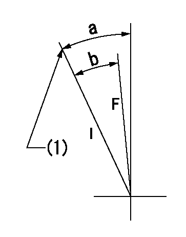
F:Full load
I:Idle
(1)Stopper bolt setting
----------
----------
a=24deg+-5deg b=21.5deg+-3deg
----------
----------
a=24deg+-5deg b=21.5deg+-3deg
Stop lever angle

N:Pump normal
S:Stop the pump.
(1)Rack position = aa
(2)Rack position bb
(3)Free (at shipping)
----------
aa=16.6mm bb=4.1-0.5mm
----------
a=35deg+-5deg b=61.5deg+7deg-5deg c=(6deg)
----------
aa=16.6mm bb=4.1-0.5mm
----------
a=35deg+-5deg b=61.5deg+7deg-5deg c=(6deg)
0000001501 LEVER

(1)Viewed from top of pump.
(2)Pump side
(3)Load control lever
(4)Adjusting bolt
(5)Nut
1. Idle increase link mechanism adjustment
(1)After completing pump and governor adjustment, fix the load control lever in the idle position.
(2)Adjust using the bolt (4) so that the idle-increase link mechanism's lever angle is a, then fix using the nut (5).
----------
----------
a=8.5deg+-3deg
----------
----------
a=8.5deg+-3deg
Timing setting

(1)Pump vertical direction
(2)Coupling's key groove position at No 1 cylinder's beginning of injection
(3)-
(4)-
----------
----------
a=(7deg)
----------
----------
a=(7deg)
Information:
Failure to follow these oil recommendations can cause shortened engine service life due to deposits and/or excessive wear.
Total Base Number (TBN) and Fuel Sulfur Levels for Direct Injection (DI) Diesel Engines
The Total Base Number (TBN) for an oil depends on the fuel sulfur level. For direct injection engines that use distillate fuel, the minimum TBN must be 10 times the fuel sulfur level. The TBN is determined by the "ASTM D2896" procedure. The minimum TBN of the oil is 5 regardless of a low fuel sulfur level. Illustration 1 demonstrates the TBN.
Illustration 1 g00104890
(Y) TBN by "ASTM D2896"
(X) Percentage of fuel sulfur by weight
(1) TBN of new oil
(2) Change the used oil when the TBN reaches this level. Use the following guidelines for fuel sulfur levels that exceed 1.5 percent:
Choose an oil with the highest TBN that meets one of these classifications:
API CG-4
API CH-4
API CI-4Note: API CH-4 oils and API CI-4 oils are acceptable if the requirements of Caterpillar's ECF-1 (Engine Crankcase Fluid specification-1) are met. CH-4 oils and CI-4 oils that have not met the requirements of Caterpillar's ECF-1 Specification may cause reduced engine life.
Reduce the oil change interval. Base the oil change interval on the oil analysis. Ensure that the oil analysis includes the condition of the oil and a wear metal analysis. Excessive piston deposits can be produced by an oil with a high TBN. These deposits can lead to a loss of control of the oil consumption and to the polishing of the cylinder bore.
Operating Direct Injection (DI) diesel engines with fuel sulfur levels over 1.0 percent may require shortened oil change intervals in order to help maintain adequate wear protection.
Lubricant Viscosity Recommendations for Direct Injection (DI) Diesel Engines
The proper SAE viscosity grade of oil is determined by the minimum ambient temperature during cold engine start-up, and the maximum ambient temperature during engine operation. Refer to Table 1 (minimum temperature) in order to determine the required oil viscosity for starting a cold engine.Refer to Table 1 (maximum temperature) in order to select the oil viscosity for engine operation at the highest ambient temperature that is anticipated.Note: Generally, use the highest oil viscosity that is available to meet the requirement for the temperature at start-up.If ambient temperature conditions at engine start-up require the use of multigrade SAE 0W oil, SAE 0W-40 viscosity grade is generally preferred over SAE 0W-20 or SAE 0W-30.Note: SAE 10W-30 is the preferred viscosity grade for the following diesel engines when the ambient temperature is above −18 °C (0 °F), and below 40 °C (104 °F).
C7
C-9
C9
3116
3126When an engine is started and an engine is operated in ambient temperatures below −20 °C (−4 °F), use multigrade oils that are capable of flowing in low temperatures.These oils have lubricant viscosity grades of SAE 0W or SAE 5W.When an engine is started and operated in ambient temperatures below −30 °C (−22 °F), use a synthetic base stock multigrade oil with a 0W viscosity grade or with a 5W viscosity grade. Use an oil with a
Have questions with 106671-7441?
Group cross 106671-7441 ZEXEL
Mitsubishi
106671-7441
ME056614
INJECTION-PUMP ASSEMBLY
6D22
6D22