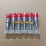
Information injection-pump assembly
BOSCH
9 400 616 937
9400616937
ZEXEL
106671-7431
1066717431
MITSUBISHI
ME056613
me056613
Rating:
Service parts 106671-7431 INJECTION-PUMP ASSEMBLY:
1.
_
7.
COUPLING PLATE
8.
_
9.
_
11.
Nozzle and Holder
ME056329
12.
Open Pre:MPa(Kqf/cm2)
17.7{180}/21.6{220}
15.
NOZZLE SET
Include in #1:
106671-7431
as INJECTION-PUMP ASSEMBLY
Cross reference number
BOSCH
9 400 616 937
9400616937
ZEXEL
106671-7431
1066717431
MITSUBISHI
ME056613
me056613
Zexel num
Bosch num
Firm num
Name
9 400 616 937
ME056613 MITSUBISHI
INJECTION-PUMP ASSEMBLY
6D22 K 14CA INJECTION PUMP ASSY PE6P,6PD PE
6D22 K 14CA INJECTION PUMP ASSY PE6P,6PD PE
Calibration Data:
Adjustment conditions
Test oil
1404 Test oil ISO4113 or {SAEJ967d}
1404 Test oil ISO4113 or {SAEJ967d}
Test oil temperature
degC
40
40
45
Nozzle and nozzle holder
105780-8140
Bosch type code
EF8511/9A
Nozzle
105780-0000
Bosch type code
DN12SD12T
Nozzle holder
105780-2080
Bosch type code
EF8511/9
Opening pressure
MPa
17.2
Opening pressure
kgf/cm2
175
Injection pipe
Outer diameter - inner diameter - length (mm) mm 8-3-600
Outer diameter - inner diameter - length (mm) mm 8-3-600
Overflow valve
131424-4620
Overflow valve opening pressure
kPa
255
221
289
Overflow valve opening pressure
kgf/cm2
2.6
2.25
2.95
Tester oil delivery pressure
kPa
157
157
157
Tester oil delivery pressure
kgf/cm2
1.6
1.6
1.6
Direction of rotation (viewed from drive side)
Right R
Right R
Injection timing adjustment
Direction of rotation (viewed from drive side)
Right R
Right R
Injection order
1-5-3-6-
2-4
Pre-stroke
mm
4.8
4.75
4.85
Beginning of injection position
Governor side NO.1
Governor side NO.1
Difference between angles 1
Cal 1-5 deg. 60 59.5 60.5
Cal 1-5 deg. 60 59.5 60.5
Difference between angles 2
Cal 1-3 deg. 120 119.5 120.5
Cal 1-3 deg. 120 119.5 120.5
Difference between angles 3
Cal 1-6 deg. 180 179.5 180.5
Cal 1-6 deg. 180 179.5 180.5
Difference between angles 4
Cyl.1-2 deg. 240 239.5 240.5
Cyl.1-2 deg. 240 239.5 240.5
Difference between angles 5
Cal 1-4 deg. 300 299.5 300.5
Cal 1-4 deg. 300 299.5 300.5
Injection quantity adjustment
Adjusting point
-
Rack position
8.1
Pump speed
r/min
700
700
700
Each cylinder's injection qty
mm3/st.
109
106.3
111.7
Basic
*
Fixing the rack
*
Standard for adjustment of the maximum variation between cylinders
*
Injection quantity adjustment_02
Adjusting point
F
Rack position
5+-0.5
Pump speed
r/min
500
500
500
Each cylinder's injection qty
mm3/st.
16.5
14
19
Fixing the rack
*
Standard for adjustment of the maximum variation between cylinders
*
Injection quantity adjustment_03
Adjusting point
A
Rack position
R1(8.1)
Pump speed
r/min
700
700
700
Average injection quantity
mm3/st.
109
108
110
Basic
*
Fixing the lever
*
Injection quantity adjustment_04
Adjusting point
C
Rack position
5.7+-0.5
Pump speed
r/min
225
225
225
Each cylinder's injection qty
mm3/st.
16.5
14
19
Fixing the rack
*
Remarks
(check)
(check)
Injection quantity adjustment_05
Adjusting point
E
Rack position
-
Pump speed
r/min
100
100
100
Average injection quantity
mm3/st.
150
110
190
Fixing the lever
*
Remarks
After startup boost setting
After startup boost setting
Timer adjustment
Pump speed
r/min
950
Advance angle
deg.
0.5
Timer adjustment_02
Pump speed
r/min
1050
Advance angle
deg.
2.2
1.7
2.7
Timer adjustment_03
Pump speed
r/min
1150
Advance angle
deg.
5.5
5
6
Remarks
Finish
Finish
Test data Ex:
Governor adjustment
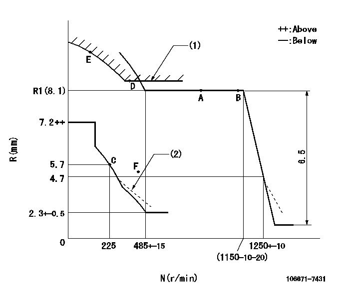
N:Pump speed
R:Rack position (mm)
(1)Excess fuel setting for starting: SXL
(2)Damper spring setting: DL
----------
SXL=R1+1+0.8mm DL=4.5-0.2mm
----------
----------
SXL=R1+1+0.8mm DL=4.5-0.2mm
----------
Speed control lever angle
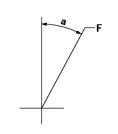
F:Full speed
----------
----------
a=27deg+-5deg
----------
----------
a=27deg+-5deg
0000000901
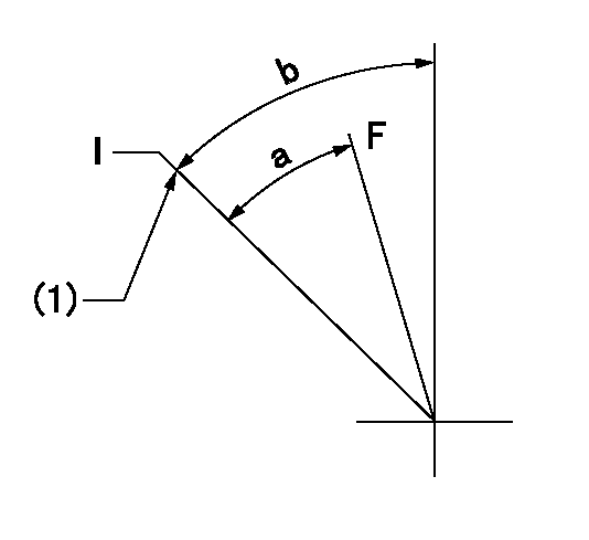
F:Full load
I:Idle
(1)Stopper bolt setting
----------
----------
a=21.5deg+-3deg b=24deg+-5deg
----------
----------
a=21.5deg+-3deg b=24deg+-5deg
Stop lever angle

N:Pump normal
S:Stop the pump.
(1)Rack position = aa
(2)Rack position = bb, set the stopper bolt.
(3)Free (at shipping)
----------
aa=16.6mm bb=4.1-0.5mm
----------
a=35deg+-5deg b=61.5deg+7deg-5deg c=(6deg)
----------
aa=16.6mm bb=4.1-0.5mm
----------
a=35deg+-5deg b=61.5deg+7deg-5deg c=(6deg)
0000001501 LEVER

(1)Viewed from top of pump.
(2)Pump side
(3)Load control lever
(4)Adjusting bolt
(5)Nut
1. Idle increase link mechanism adjustment
(1)After completing pump and governor adjustment, fix the load control lever in the idle position.
(2)Adjust using the bolt (4) so that the idle-increase link mechanism's lever angle is a, then fix using the nut (5).
----------
----------
a=8.5deg+-3deg
----------
----------
a=8.5deg+-3deg
0000001601 MICRO SWITCH
Adjustment of the micro-switch
Adjust the bolt to obtain the following lever position when the micro-switch is ON.
(1)Speed N1
(2)Rack position Ra
----------
N1=325+-5r/min Ra=5.4mm
----------
----------
N1=325+-5r/min Ra=5.4mm
----------
Timing setting

(1)Pump vertical direction
(2)Coupling's key groove position at No 1 cylinder's beginning of injection
(3)-
(4)-
----------
----------
a=(7deg)
----------
----------
a=(7deg)
Information:
Do not use a commercial coolant/antifreeze that only meets the ASTM "D3306" specification. This type of coolant/antifreeze is made for light duty automotive applications.Use only the coolant/antifreeze that is recommended.
Note: Caterpillar recommends a 1:1 mixture of water and glycol. This mixture of water and glycol will provide optimum heavy-duty performance as a coolant/antifreeze.Note: Caterpillar DEAC DOES NOT require a treatment with an Supplemental Coolant Additive (SCA) at the initial fill. Commercial heavy-duty coolant/antifreeze that meets "ASTM D4985" or "ASTM D6210" specifications MAY require a treatment with a supplemental coolant additive at the initial fill. Read the label or the instructions that are provided by the OEM of the product.Note: These coolants WILL require a treatment with a supplemental coolant additive on a maintenance basis. Regardless of the ambient temperature, the supplemental coolant additive should be maintained between three to six percent. The Caterpillar 4C-9297 Test Strip can be used to help maintain the appropriate concentration of Caterpillar SCA.
All Caterpillar diesel engines equipped with air-to-air aftercooling (ATAAC) require a minimum of 30 percent glycol to prevent water pump cavitation.
Glycol
For optimum performance, Caterpillar recommends a 1:1 mixture of a water/glycol solution.Note: Use a mixture that will provide protection against the lowest ambient temperature.Note: 100 percent pure glycol will freeze at a temperature of −23 °C (−9 °F).
Table 1
Ethylene Glycol
Concentration Freeze Protection Boil Protection
50 Percent −36 °C (−33 °F) 106 °C (223 °F)
60 Percent −52 °C (−62 °F) 111 °C (232 °F) Check the coolant for the concentration of glycol frequently in cold weather with a refractometer type coolant tester in order to ensure adequate freeze protection.To check the concentration of glycol, use the 1U-7298 Coolant/Battery Tester (DEGREES CELSIUS) or use the 1U-7297 Coolant/Battery Tester (DEGREES FAHRENHEIT). The testers give readings that are immediate and accurate. The testers can be used with ethylene or propylene glycol.Water
Distilled water or deionized water is recommended for use in engine cooling systems. DO NOT use the following types of water in cooling systems: hard water, softened water that has been conditioned with salt, and sea water. Damage to the cooling system may result.
Note: If distilled water or deionized water is not available, use water with the properties that are listed in table 2.
Table 2
Caterpillar Minimum Acceptable Water Requirements
Property Maximum ASTM Specification
Chloride (Cl) 40 mg/L (2.4 grains per US gal) "D512"
"D4327"
Sulfate (SO4) 100 mg/L (5.9 grains per US gal) "D516"
Total Hardness 170 mg/L (10 grains per US gal) "D1126"
Total Solids 340 mg/L (20 grains per US gal) "D1888"
Acidity pH of 5.5 to 9.0 "D1293"
