Information injection-pump assembly
ZEXEL
106671-7330
1066717330
MITSUBISHI-HEAV
3256510160
3256510160

Rating:
Cross reference number
ZEXEL
106671-7330
1066717330
MITSUBISHI-HEAV
3256510160
3256510160
Zexel num
Bosch num
Firm num
Name
Calibration Data:
Adjustment conditions
Test oil
1404 Test oil ISO4113 or {SAEJ967d}
1404 Test oil ISO4113 or {SAEJ967d}
Test oil temperature
degC
40
40
45
Nozzle and nozzle holder
105780-8130
Bosch type code
EFEP215A
Nozzle
105780-0050
Bosch type code
DN6TD119NP1T
Nozzle holder
105780-2090
Bosch type code
EFEP215
Opening pressure
MPa
17.2
Opening pressure
kgf/cm2
175
Injection pipe
Outer diameter - inner diameter - length (mm) mm 8-3-600
Outer diameter - inner diameter - length (mm) mm 8-3-600
Overflow valve
131424-3720
Overflow valve opening pressure
kPa
255
221
289
Overflow valve opening pressure
kgf/cm2
2.6
2.25
2.95
Tester oil delivery pressure
kPa
157
157
157
Tester oil delivery pressure
kgf/cm2
1.6
1.6
1.6
Direction of rotation (viewed from drive side)
Left L
Left L
Injection timing adjustment
Direction of rotation (viewed from drive side)
Left L
Left L
Injection order
1-5-3-6-
2-4
Pre-stroke
mm
2.7
2.65
2.75
Rack position
Point A R=A
Point A R=A
Beginning of injection position
Governor side NO.1
Governor side NO.1
Difference between angles 1
Cal 1-5 deg. 60 59.5 60.5
Cal 1-5 deg. 60 59.5 60.5
Difference between angles 2
Cal 1-3 deg. 120 119.5 120.5
Cal 1-3 deg. 120 119.5 120.5
Difference between angles 3
Cal 1-6 deg. 180 179.5 180.5
Cal 1-6 deg. 180 179.5 180.5
Difference between angles 4
Cyl.1-2 deg. 240 239.5 240.5
Cyl.1-2 deg. 240 239.5 240.5
Difference between angles 5
Cal 1-4 deg. 300 299.5 300.5
Cal 1-4 deg. 300 299.5 300.5
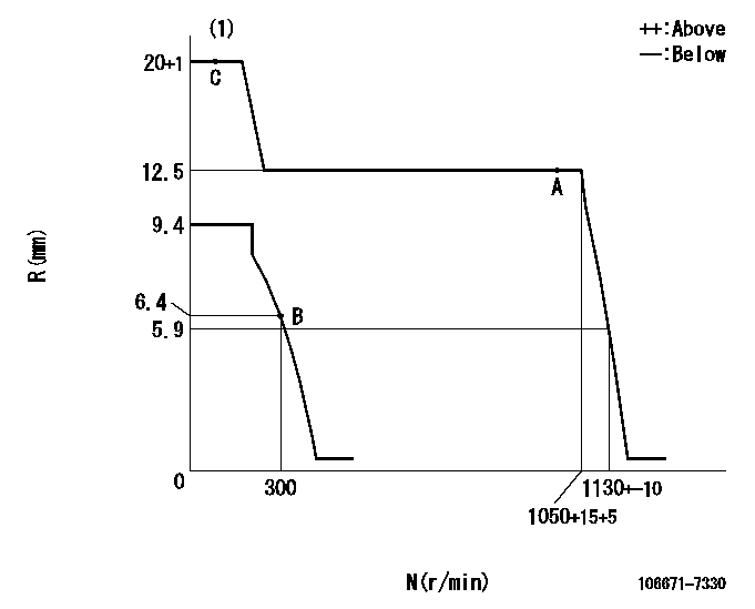
Injection quantity adjustment
Adjusting point
A
Rack position
12.5
Pump speed
r/min
1000
1000
1000
Average injection quantity
mm3/st.
373
364
382
Max. variation between cylinders
%
0
-3
3
Basic
*
Fixing the lever
*
Injection quantity adjustment_02
Adjusting point
B
Rack position
6.4+-0.5
Pump speed
r/min
300
300
300
Average injection quantity
mm3/st.
67.1
64.1
70.1
Max. variation between cylinders
%
0
-10
10
Fixing the rack
*
Timer adjustment
Pump speed
r/min
400
Advance angle
deg.
0.5
Timer adjustment_02
Pump speed
r/min
700
Advance angle
deg.
1.2
0.7
1.7
Timer adjustment_03
Pump speed
r/min
1050
Advance angle
deg.
3.5
3
4
Timer adjustment_04
Pump speed
r/min
-
Advance angle
deg.
4
4
4
Remarks
Measure the actual speed, stop
Measure the actual speed, stop
Test data Ex:
Governor adjustment
N:Pump speed
R:Rack position (mm)
(1)Target notch: K
----------
K=4
----------
----------
K=4
----------
Speed control lever angle
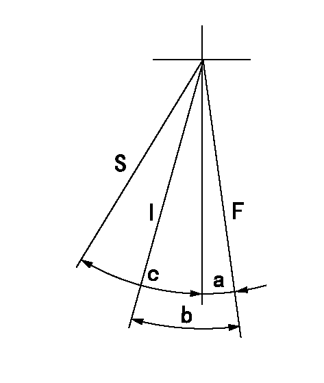
F:Full speed
I:Idle
S:Stop
----------
----------
a=(1deg)+-5deg b=(25deg)+-5deg c=32deg+-3deg
----------
----------
a=(1deg)+-5deg b=(25deg)+-5deg c=32deg+-3deg
Stop lever angle
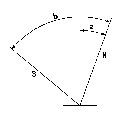
N:Pump normal
S:Stop the pump.
----------
----------
a=20deg+-5deg b=72deg+-5deg
----------
----------
a=20deg+-5deg b=72deg+-5deg
Timing setting

(1)Pump vertical direction
(2)Coupling's key groove position at No 1 cylinder's beginning of injection
(3)-
(4)-
----------
----------
a=(20deg)
----------
----------
a=(20deg)
Information:
Disconnect all electrical power from the monitor before removing components. Failure to disconnect the power could result in severe electrical shock or damage to the monitor. An electrical shock can cause severe personal injury or death.
Choose the appropriate drive for your monitor from the table below. The 203-7811 Engine Monitoring Control Group uses Wonderware as the "Graphic Display Application". The 203-7810 Engine Monitoring Control Group uses RSView as the "Graphic Display Application".
Table 1
Drive "Graphic Display Application"
203-7816 Storage Drive RSView
204-8792 Storage Drive Wonderware In order to install the drive, perform the procedure that follows:
Connect the ribbon cable connector and power cables to the hard drive and the floppy disk drive.Note: Make sure that the ribbon cable is correctly installed. The connector must be positioned so that the red wire of the cable is closest to the back of the unit. If you are using the new cables, also connect the other end of the cables to the Central Processing Unit (CPU) card.
Illustration 1 g00858453
(1) Drive Bay Mounting Studs
Position the drive bay into the chassis so that the studs (1) on the chassis fit into the grommets on the drive bay.Note: Be careful not to push the vibration dampers (grommets) on the drive bay out of the sheet metal.
Install the back cover.
Apply power and verify the operation of the drive. Refer to any additional instructions that are provided with the drive.