Information injection-pump assembly
ZEXEL
106671-7220
1066717220
Rating:
Cross reference number
ZEXEL
106671-7220
1066717220
Zexel num
Bosch num
Firm num
Name
Calibration Data:
Adjustment conditions
Test oil
1404 Test oil ISO4113 or {SAEJ967d}
1404 Test oil ISO4113 or {SAEJ967d}
Test oil temperature
degC
40
40
45
Nozzle and nozzle holder
105780-8130
Bosch type code
EFEP215A
Nozzle
105780-0050
Bosch type code
DN6TD119NP1T
Nozzle holder
105780-2090
Bosch type code
EFEP215
Opening pressure
MPa
17.2
Opening pressure
kgf/cm2
175
Injection pipe
Outer diameter - inner diameter - length (mm) mm 8-3-600
Outer diameter - inner diameter - length (mm) mm 8-3-600
Overflow valve
131424-4620
Overflow valve opening pressure
kPa
255
221
289
Overflow valve opening pressure
kgf/cm2
2.6
2.25
2.95
Tester oil delivery pressure
kPa
157
157
157
Tester oil delivery pressure
kgf/cm2
1.6
1.6
1.6
Direction of rotation (viewed from drive side)
Right R
Right R
Injection timing adjustment
Direction of rotation (viewed from drive side)
Right R
Right R
Injection order
1-5-3-6-
2-4
Pre-stroke
mm
4.8
4.75
4.85
Beginning of injection position
Governor side NO.1
Governor side NO.1
Difference between angles 1
Cal 1-5 deg. 60 59.5 60.5
Cal 1-5 deg. 60 59.5 60.5
Difference between angles 2
Cal 1-3 deg. 120 119.5 120.5
Cal 1-3 deg. 120 119.5 120.5
Difference between angles 3
Cal 1-6 deg. 180 179.5 180.5
Cal 1-6 deg. 180 179.5 180.5
Difference between angles 4
Cyl.1-2 deg. 240 239.5 240.5
Cyl.1-2 deg. 240 239.5 240.5
Difference between angles 5
Cal 1-4 deg. 300 299.5 300.5
Cal 1-4 deg. 300 299.5 300.5
Injection quantity adjustment
Adjusting point
-
Rack position
11.2
Pump speed
r/min
700
700
700
Each cylinder's injection qty
mm3/st.
251.2
244.9
257.5
Basic
*
Fixing the rack
*
Standard for adjustment of the maximum variation between cylinders
*
Injection quantity adjustment_02
Adjusting point
F
Rack position
5+-0.5
Pump speed
r/min
500
500
500
Each cylinder's injection qty
mm3/st.
12.4
10.5
14.3
Fixing the rack
*
Standard for adjustment of the maximum variation between cylinders
*
Injection quantity adjustment_03
Adjusting point
A
Rack position
R1(11.2)
Pump speed
r/min
700
700
700
Average injection quantity
mm3/st.
251.2
250.2
252.2
Basic
*
Fixing the lever
*
Boost pressure
kPa
60
60
Boost pressure
mmHg
450
450
Injection quantity adjustment_04
Adjusting point
B
Rack position
R1(10.2)
Pump speed
r/min
1100
1100
1100
Average injection quantity
mm3/st.
254.5
252.5
256.5
Difference in delivery
mm3/st.
9.2
9.2
9.2
Fixing the lever
*
Boost pressure
kPa
60
60
Boost pressure
mmHg
450
450
Injection quantity adjustment_05
Adjusting point
C
Rack position
5.7+-0.5
Pump speed
r/min
225
225
225
Each cylinder's injection qty
mm3/st.
20
17
23
Fixing the rack
*
Boost pressure
kPa
0
0
0
Boost pressure
mmHg
0
0
0
Remarks
(check)
(check)
Injection quantity adjustment_06
Adjusting point
D
Rack position
R3(8.3)
Pump speed
r/min
500
500
500
Average injection quantity
mm3/st.
136.5
132.7
140.3
Fixing the lever
*
Boost pressure
kPa
0
0
0
Boost pressure
mmHg
0
0
0
Injection quantity adjustment_07
Adjusting point
E
Rack position
-
Pump speed
r/min
100
100
100
Average injection quantity
mm3/st.
151
131
171
Fixing the lever
*
Boost compensator adjustment
Pump speed
r/min
600
600
600
Rack position
R3(8.3)
Boost pressure
kPa
6.7
6.7
6.7
Boost pressure
mmHg
50
50
50
Boost compensator adjustment_02
Pump speed
r/min
600
600
600
Rack position
8.9
Boost pressure
kPa
12.7
12.7
12.7
Boost pressure
mmHg
95
95
95
Boost compensator adjustment_03
Pump speed
r/min
600
600
600
Rack position
9.9
Boost pressure
kPa
24.7
23.4
26
Boost pressure
mmHg
185
175
195
Boost compensator adjustment_04
Pump speed
r/min
600
600
600
Rack position
R1(11.2)
Boost pressure
kPa
44.7
44.7
44.7
Boost pressure
mmHg
335
335
335
Test data Ex:
Governor adjustment
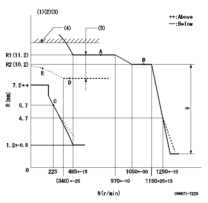
N:Pump speed
R:Rack position (mm)
(1)Lever ratio: RT
(2)Target shim dimension: TH
(3)Damper spring setting: DL
(4)RACK LIMIT: RAL
(5)Boost compensator stroke: BCL
----------
RT=1 TH=2.5mm DL=4.5-0.2mm RAL=11.5+-0.1mm BCL=(2.9)+-0.1mm
----------
----------
RT=1 TH=2.5mm DL=4.5-0.2mm RAL=11.5+-0.1mm BCL=(2.9)+-0.1mm
----------
Timer adjustment
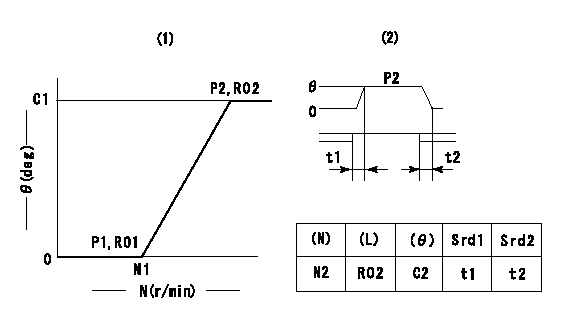
(1)Adjusting range
(2)Step response time
(N): Speed of the pump
(L): Load
(theta) Advance angle
(Srd1) Step response time 1
(Srd2) Step response time 2
1. Adjusting conditions for the variable timer
(1)Adjust the clearance between the pickup and the protrusion to L.
----------
L=1-0.2mm N2=800r/min C2=(8)deg t1=2.5--sec. t2=2.5--sec.
----------
N1=1100++r/min P1=0kPa(0kgf/cm2) P2=392kPa(4kgf/cm2) C1=8+-0.3deg R01=0/4load R02=4/4load
----------
L=1-0.2mm N2=800r/min C2=(8)deg t1=2.5--sec. t2=2.5--sec.
----------
N1=1100++r/min P1=0kPa(0kgf/cm2) P2=392kPa(4kgf/cm2) C1=8+-0.3deg R01=0/4load R02=4/4load
Speed control lever angle
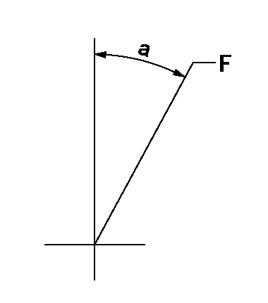
F:Full speed
----------
----------
a=17deg+-5deg
----------
----------
a=17deg+-5deg
0000000901
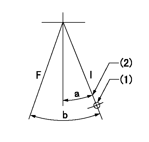
F:Full load
I:Idle
(1)Use the hole at R = aa
(2)Stopper bolt setting
----------
aa=46mm
----------
a=28deg+-5deg b=37deg+-3deg
----------
aa=46mm
----------
a=28deg+-5deg b=37deg+-3deg
Stop lever angle
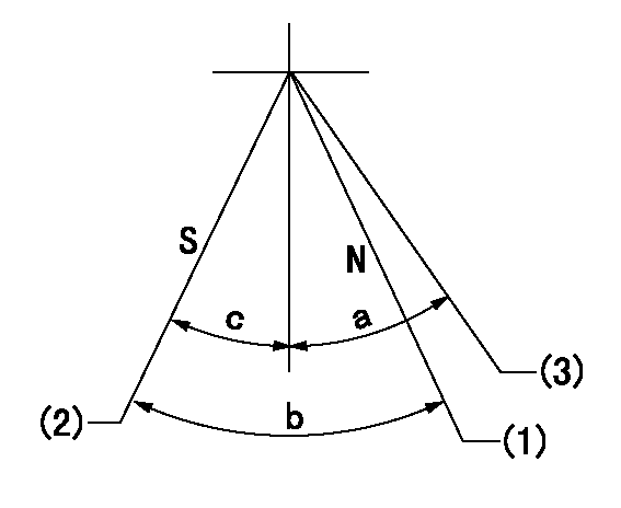
N:Pump normal
S:Stop the pump.
(1)Rack position = aa
(2)Set stopper bolt so that rack position = bb.
(3)Free (at shipping)
----------
aa=13.3mm bb=4.1-0.5mm
----------
a=(38deg) b=26deg+-5deg c=0deg+7deg-5deg
----------
aa=13.3mm bb=4.1-0.5mm
----------
a=(38deg) b=26deg+-5deg c=0deg+7deg-5deg
0000001501 RACK SENSOR

V1:Supply voltage
V2f:Full side output voltage
V2i:Idle side output voltage
(A) Black
(B) Yellow
(C) Red
(D) Trimmer
(E): Shaft
(F) Nut
(G) Load lever
1. Load sensor adjustment
(1)Connect as shown in the above diagram and apply supply voltage V1.
(2)Hold the load lever (G) against the full side.
(3)Turn the shaft so that the voltage between (A) and (B) is V2.
(4)Hold the load lever (G) against the idle side.
(5)Adjust (D) so that the voltage between (A) and (B) is V2i.
(6)Repeat the above adjustments.
(7)Tighten the nut (F) at the point satisfying the standards.
(8)Hold the load lever against the full side stopper and the idle side stopper.
(9)At this time, confirm that the full side output voltage is V2f and the idle side output voltage is V2i.
----------
V1= 5+-0.02V V2f=0.15+0.03V V2i=2.35-0.03V
----------
----------
V1= 5+-0.02V V2f=0.15+0.03V V2i=2.35-0.03V
----------
0000001601 MICRO SWITCH
Exhaust brake switch adjustment
Adjust the bolt to obtain the lower lever position when the exhaust brake switch is ON.
(1)Speed N1
(2)Rack position Ra
----------
N1=325+-5r/min Ra=5.4mm
----------
----------
N1=325+-5r/min Ra=5.4mm
----------
0000001701 MICRO SWITCH
Load microswitch adjustment
With the microswitch ON, adjust the bolt so that the bottom lever contacts the stopper.
(1)Speed N1
(2)Rack position Ra
----------
N1=600+-5r/min Ra=7.7mm
----------
----------
N1=600+-5r/min Ra=7.7mm
----------
Timing setting

(1)Pump vertical direction
(2)Coupling's key groove position at No 1 cylinder's beginning of injection
(3)-
(4)-
----------
----------
a=(7deg)
----------
----------
a=(7deg)
Information:
Introduction
The problem that is identified below does not have a known permanent solution. Until a permanent solution is known, use the solution that is identified below.Problem
Caterpillar has discovered that when certain products equipped with the Caterpillar Regeneration System (CRS) are left idling for extended periods of time (greater than 1 hr) and ambient temps are lower than −15° C (5° F), certain conditions may be met which will disable the ability to regenerate the DPF. If the regeneration system cannot activate, the DPF will accumulate too much soot and must eventually be replaced.The issues Caterpillar has identified in extreme cold ambient conditions are the coolant temperature may become too cold for the regeneration system to activate. Also, the pressure lines which connect the DPF inlet section to the DPF intake pressure sensor may collect condensation and freeze. This freezing causes an E1154 (2) or 3609-18 Low DPF #1 Intake Pressure event code. The event code will disable the regeneration until the fault condition goes away.If you suspect low coolant temperature may be contributing to an inability to regenerate the DPF, review the product status report. The product status report is used for investigating the following fault code trend. If coolant temp is the only issue, you will likely see a combination of the following fault codes:
E995 (2) High DPF #1 Soot Loading or 3719-16 Particulate Trap #1 Soot Load Percent : High - moderate severity (2)
Indicates DPF soot load percent has reached 100 percent
E995(3) High DPF #1 soot loading or 3719-0 Particulate Trap #1 Soot Load Percent : High - most severe (3)
Indicates DPF soot load percent has reached 116 percent
E992(3) DPF Active Regeneration Inhibited Due to Temporary System Lockout or 3714-31 Particulate Trap Active Regeneration Inhibited Due to Temporary System Lockout
Indicates DPF soot load reached 116 percent and 10 minutes has passed since that point. Ability to perform automatic or manual regenerations is disabled. Caterpillar Electronic Technician (ET) regeneration is only type of regeneration allowed.
E991 (3) DPF Active Regeneration Inhibited Due to Permanent System Lockout or 3715-31 Particulate Trap Active Regeneration Inhibited Due to Permanent System Lockout
Indicates DPF soot load percent has reached 140 percent. All types of regeneration are disabled. DPF must be replaced as the amount of soot load will damage the DPF if ignited by regeneration process.If you suspect the pressure line for the DPF intake pressure has frozen, you will see a combination of fault codes. These codes will consist of the codes listed above with the addition of the following codes: E1154 (2) DPF #1 intake pressure low and 3609-18 DPF #1 Intake Pressure : Low - moderate severity (2).Solution
Caterpillar recommends the following when extended idling is likely to occur and ambient temperatures are less than −15° C (5° F):
Turn off machine before the end of shift. Before shutting down, perform a manual DPF regeneration and reduce soot load to 0 percent. The soot load must be above the 15 percent threshold needed to activate a manual DPF regeneration.If extended idling is