Information injection-pump assembly
ZEXEL
106671-7170
1066717170
MITSUBISHI-HEAV
3256520060
3256520060

Rating:
Service parts 106671-7170 INJECTION-PUMP ASSEMBLY:
1.
_
2.
FUEL INJECTION PUMP
7.
COUPLING PLATE
8.
_
9.
_
11.
Nozzle and Holder
12.
Open Pre:MPa(Kqf/cm2)
29.4{300}
15.
NOZZLE SET
Include in #1:
106671-7170
as INJECTION-PUMP ASSEMBLY
Cross reference number
ZEXEL
106671-7170
1066717170
MITSUBISHI-HEAV
3256520060
3256520060
Zexel num
Bosch num
Firm num
Name
Calibration Data:
Adjustment conditions
Test oil
1404 Test oil ISO4113 or {SAEJ967d}
1404 Test oil ISO4113 or {SAEJ967d}
Test oil temperature
degC
40
40
45
Nozzle and nozzle holder
105780-8130
Bosch type code
EFEP215A
Nozzle
105780-0050
Bosch type code
DN6TD119NP1T
Nozzle holder
105780-2090
Bosch type code
EFEP215
Opening pressure
MPa
17.2
Opening pressure
kgf/cm2
175
Injection pipe
Outer diameter - inner diameter - length (mm) mm 8-3-600
Outer diameter - inner diameter - length (mm) mm 8-3-600
Overflow valve
131424-3720
Overflow valve opening pressure
kPa
255
221
289
Overflow valve opening pressure
kgf/cm2
2.6
2.25
2.95
Tester oil delivery pressure
kPa
157
157
157
Tester oil delivery pressure
kgf/cm2
1.6
1.6
1.6
Direction of rotation (viewed from drive side)
Left L
Left L
Injection timing adjustment
Direction of rotation (viewed from drive side)
Left L
Left L
Injection order
1-5-3-6-
2-4
Pre-stroke
mm
2.7
2.65
2.75
Rack position
Point A R=A
Point A R=A
Beginning of injection position
Governor side NO.1
Governor side NO.1
Difference between angles 1
Cal 1-5 deg. 60 59.5 60.5
Cal 1-5 deg. 60 59.5 60.5
Difference between angles 2
Cal 1-3 deg. 120 119.5 120.5
Cal 1-3 deg. 120 119.5 120.5
Difference between angles 3
Cal 1-6 deg. 180 179.5 180.5
Cal 1-6 deg. 180 179.5 180.5
Difference between angles 4
Cyl.1-2 deg. 240 239.5 240.5
Cyl.1-2 deg. 240 239.5 240.5
Difference between angles 5
Cal 1-4 deg. 300 299.5 300.5
Cal 1-4 deg. 300 299.5 300.5
Injection quantity adjustment
Adjusting point
A
Rack position
12.5
Pump speed
r/min
1000
1000
1000
Average injection quantity
mm3/st.
373
364
382
Max. variation between cylinders
%
0
-3
3
Basic
*
Fixing the lever
*
Injection quantity adjustment_02
Adjusting point
B
Rack position
6.4+-0.5
Pump speed
r/min
300
300
300
Average injection quantity
mm3/st.
67.1
64.1
70.1
Max. variation between cylinders
%
0
-10
10
Fixing the rack
*
Timer adjustment
Pump speed
r/min
400
Advance angle
deg.
0.5
Timer adjustment_02
Pump speed
r/min
700
Advance angle
deg.
1.2
0.7
1.7
Timer adjustment_03
Pump speed
r/min
1050
Advance angle
deg.
3.5
3
4
Timer adjustment_04
Pump speed
r/min
-
Advance angle
deg.
4
4
4
Remarks
Measure the actual speed, stop
Measure the actual speed, stop
Test data Ex:
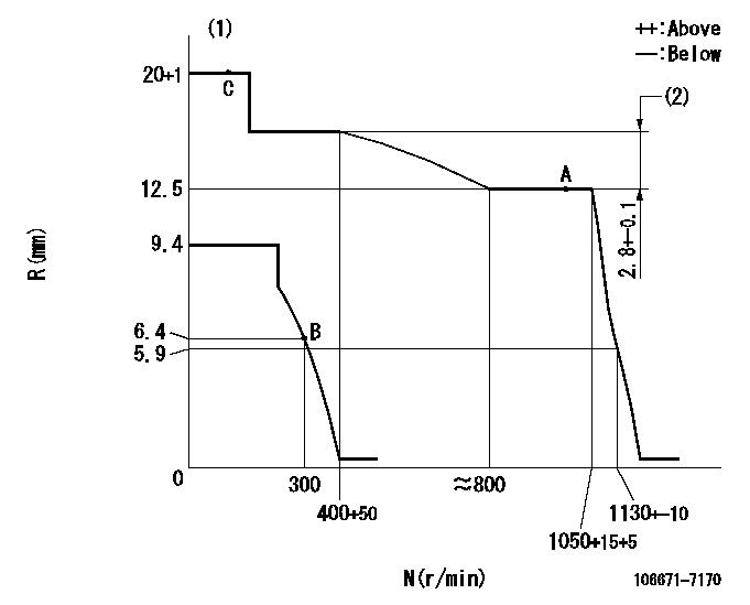
Governor adjustment

N:Pump speed
R:Rack position (mm)
(1)Target notch: K
(2)Rack difference between N = N1 and N = N2
----------
K=8 N1=1000r/min N2=350r/min
----------
----------
K=8 N1=1000r/min N2=350r/min
----------
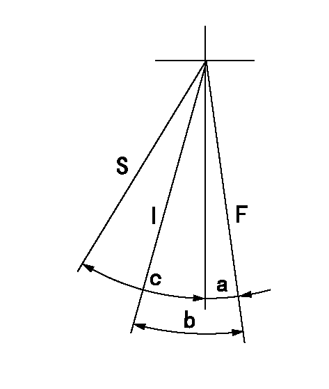
Speed control lever angle

F:Full speed
I:Idle
S:Stop
----------
----------
a=7deg+-5deg b=29deg+-5deg c=32deg+-3deg
----------
----------
a=7deg+-5deg b=29deg+-5deg c=32deg+-3deg
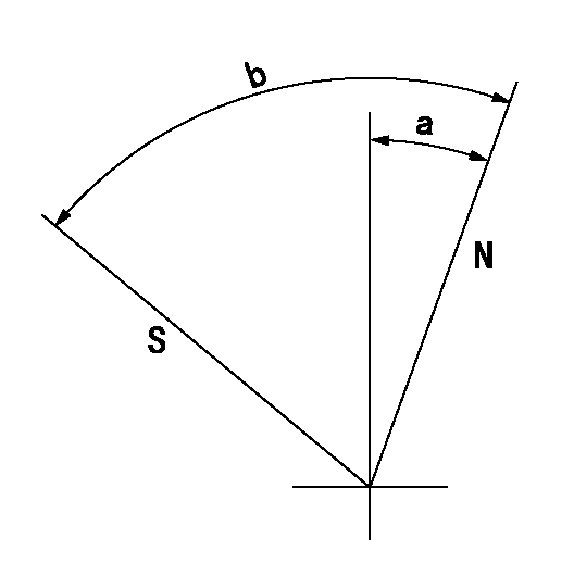
Stop lever angle

N:Pump normal
S:Stop the pump.
----------
----------
a=20deg+-5deg b=72deg+-5deg
----------
----------
a=20deg+-5deg b=72deg+-5deg
Timing setting

(1)Pump vertical direction
(2)Coupling's key groove position at No 1 cylinder's beginning of injection
(3)-
(4)-
----------
----------
a=(20deg)
----------
----------
a=(20deg)
Information:
Table 1
Additional Troubleshooting
Problem Possible Explanation Required Action
Direct Connections
PC unable to connect to CCM PC is configured improperly, or a cable error is present. Determine if the proper serial port on the PC has been selected. Make sure the correct RS-232C cable is being used. Null modem cable is required. Match the PC configuration with the CCM configuration.
Modem Connections
PC unable to connect to CCM PC configured improperly, modem not set up properly, or cable error is present. PC modem and CCM modem are not compatible.
Password was not entered within 60 seconds Determine if proper serial port on the PC is selected. Make sure that the Communication Specifications are being met and consult the modem manual. Make sure the correct RS-232C cable is being used. No null modem is required. Match the CCM, PC, and modem configurations.
Modem does not answer Improper modem configuration. Verify that the modem is configured per the instructions given in the Communication Initialization section in this manual.
Modem disconnects during remote start. System battery voltage is low. Make sure that the (+/-) Battery Power Specifications are being met. It may be necessary to disconnect the phone line on the local modem temporarily to force it to hang up.
Direct or Modem Connections
PC can connect to only one electronic controller in a multiple unit installation. Electronic controller MID has not been programmed.
Electronic controllers are not connected on the correct data link. Refer to Programming the Engine Number section and Data Link Guidelines section in this manual.
PC will not connect to 3500B marine propulsion engine through the CCM PC software. CCM has been installed on the wrong data link. CCM PC software version 1.2 and earlier will not communicate with the CCM if the CCM is connected via the primary Data Link on 3500B Marine Engines built after 4/97. The CCM should be connected to the Secondary CAT Data Link on these engines when used as a communications interface. Refer to the Data Link Guidelines section in this manual.