Information injection-pump assembly
BOSCH
9 400 613 008
9400613008
ZEXEL
106671-6452
1066716452
ISUZU
1156033342
1156033342
Rating:
Compare Prices: .
As an associate, we earn commssions on qualifying purchases through the links below

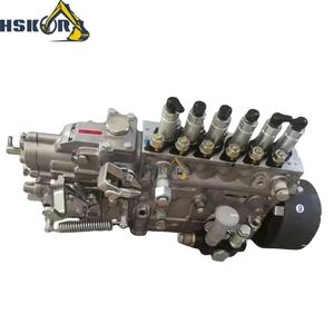
Fuel Injection Pump 1156033342 for Isuzu Engine 6HK1 Hitachi Excavator ZX330-3G ZX350-5G ZX350H ZX350K ZX350W ZX500W ZX360LC-HHE
DIGERTECH Part number:1156033342 || Application: for Isuzu Engine 6HK1 Hitachi Excavator ZX330-3G ZX350-5G ZX350H ZX350K ZX350W ZX500W ZX360LC-HHE
DIGERTECH Part number:1156033342 || Application: for Isuzu Engine 6HK1 Hitachi Excavator ZX330-3G ZX350-5G ZX350H ZX350K ZX350W ZX500W ZX360LC-HHE

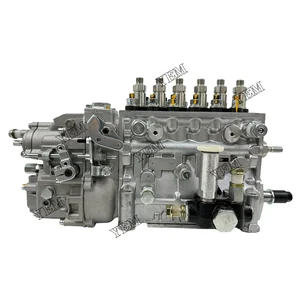
Fuel Injection Pump Fits Compatible with Isuzu Engine 6HK1 106671-6452 106067-6251 1066716452
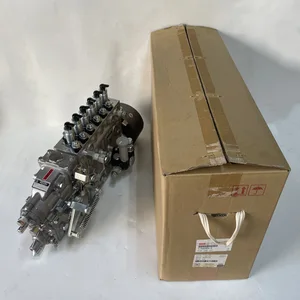
EWAIDI Part Number: 106671-6452 106067-6251 1066716452 Note: Please check the fitment carefully before purchase. Or just tell us the part number you need. || Part Name: Fuel Injection Pump || Suitable for use with the Isuzu Engine 6HK1. || Package included: 1 piece of the Fuel Injection Pump with model numbers 106671-6452, 106067-6251, and 1066716452. This essential component is designed to efficiently deliver fuel to the engine for optimal performance. A high-quality and durable product that is essential for maintaining the proper functioning of your vehicle.
EWAIDI Part Number: 106671-6452 106067-6251 1066716452 Note: Please check the fitment carefully before purchase. Or just tell us the part number you need. || Part Name: Fuel Injection Pump || Suitable for use with the Isuzu Engine 6HK1. || Package included: 1 piece of the Fuel Injection Pump with model numbers 106671-6452, 106067-6251, and 1066716452. This essential component is designed to efficiently deliver fuel to the engine for optimal performance. A high-quality and durable product that is essential for maintaining the proper functioning of your vehicle.
Compatible with Isuzu Engine 6HK1 Compatible Fuel Injection Pump 106671-6452 106067-6251 1066716452
EWAIDI Part Number: 106671-6452 106067-6251 1066716452 Note: Please check the fitment carefully before purchase. Or just tell us the part number you need. || Part Name: Fuel Injection Pump || Suitable for use with the Isuzu Engine 6HK1 || Package included: 1 piece of the Fuel Injection Pump with model numbers 106671-6452, 106067-6251, and 1066716452. This essential component is designed to efficiently deliver fuel to the engine for optimal performance. A high-quality and durable product that is essential for maintaining the proper functioning of your vehicle.
EWAIDI Part Number: 106671-6452 106067-6251 1066716452 Note: Please check the fitment carefully before purchase. Or just tell us the part number you need. || Part Name: Fuel Injection Pump || Suitable for use with the Isuzu Engine 6HK1 || Package included: 1 piece of the Fuel Injection Pump with model numbers 106671-6452, 106067-6251, and 1066716452. This essential component is designed to efficiently deliver fuel to the engine for optimal performance. A high-quality and durable product that is essential for maintaining the proper functioning of your vehicle.
You can express buy:
USD 969.65
01-07-2025
01-07-2025
Fuel Injection Pump Assy New 6HK1 for Isuzu ZEXEL 1156033345 1156033342 for Excavator Manufacturing Plant
USD 1207.2
13-05-2025
13-05-2025
Long Time Aftersale Service Fuel Injection Pump 106671-6452 For Isuzu 6HK1 Engine Spare Parts
USD 2025.65
19-05-2025
19-05-2025
Sany Excavator Diesel Pump High Pressure Oil Pump115603-3342 1-15603334-2 Original Accessories
Images:
USD 1328.62

[14-Jun-2025]
USD 2028.98

[28-Apr-2025]
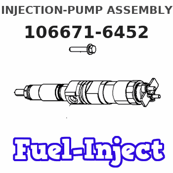
Service parts 106671-6452 INJECTION-PUMP ASSEMBLY:
1.
_

7.
COUPLING PLATE
8.
_
9.
_
11.
Nozzle and Holder
1-15300-389-1
12.
Open Pre:MPa(Kqf/cm2)
18.1{185}/22.1{225}
14.
NOZZLE
Include in #1:
106671-6452
as INJECTION-PUMP ASSEMBLY
Cross reference number
BOSCH
9 400 613 008
9400613008
ZEXEL
106671-6452
1066716452
ISUZU
1156033342
1156033342
Zexel num
Bosch num
Firm num
Name
106671-6452
9 400 613 008
1156033342 ISUZU
INJECTION-PUMP ASSEMBLY
6HK1-XQA K 14CA INJECTION PUMP ASSY PE6P,6PD PE
6HK1-XQA K 14CA INJECTION PUMP ASSY PE6P,6PD PE
Calibration Data:
Adjustment conditions
Test oil
1404 Test oil ISO4113 or {SAEJ967d}
1404 Test oil ISO4113 or {SAEJ967d}
Test oil temperature
degC
40
40
45
Nozzle and nozzle holder
105780-8140
Bosch type code
EF8511/9A
Nozzle
105780-0000
Bosch type code
DN12SD12T
Nozzle holder
105780-2080
Bosch type code
EF8511/9
Opening pressure
MPa
17.2
Opening pressure
kgf/cm2
175
Injection pipe
Outer diameter - inner diameter - length (mm) mm 8-3-600
Outer diameter - inner diameter - length (mm) mm 8-3-600
Overflow valve
134424-4320
Overflow valve opening pressure
kPa
255
221
289
Overflow valve opening pressure
kgf/cm2
2.6
2.25
2.95
Tester oil delivery pressure
kPa
255
255
255
Tester oil delivery pressure
kgf/cm2
2.6
2.6
2.6
Direction of rotation (viewed from drive side)
Left L
Left L
Injection timing adjustment
Direction of rotation (viewed from drive side)
Left L
Left L
Injection order
1-5-3-6-
2-4
Pre-stroke
mm
2.9
2.87
2.93
Beginning of injection position
Governor side NO.1
Governor side NO.1
Difference between angles 1
Cal 1-5 deg. 60 59.75 60.25
Cal 1-5 deg. 60 59.75 60.25
Difference between angles 2
Cal 1-3 deg. 120 119.75 120.25
Cal 1-3 deg. 120 119.75 120.25
Difference between angles 3
Cal 1-6 deg. 180 179.75 180.25
Cal 1-6 deg. 180 179.75 180.25
Difference between angles 4
Cyl.1-2 deg. 240 239.75 240.25
Cyl.1-2 deg. 240 239.75 240.25
Difference between angles 5
Cal 1-4 deg. 300 299.75 300.25
Cal 1-4 deg. 300 299.75 300.25
Injection quantity adjustment
Adjusting point
A
Rack position
12.8
Pump speed
r/min
1000
1000
1000
Average injection quantity
mm3/st.
133.5
132.5
134.5
Max. variation between cylinders
%
0
-3
3
Basic
*
Fixing the lever
*
Boost pressure
kPa
171
171
Boost pressure
mmHg
1280
1280
Injection quantity adjustment_02
Adjusting point
-
Rack position
7.5+-0.5
Pump speed
r/min
500
500
500
Average injection quantity
mm3/st.
9.5
6.3
12.7
Max. variation between cylinders
%
0
-15
15
Fixing the rack
*
Boost pressure
kPa
0
0
0
Boost pressure
mmHg
0
0
0
Remarks
Adjust only variation between cylinders; adjust governor according to governor specifications.
Adjust only variation between cylinders; adjust governor according to governor specifications.
Injection quantity adjustment_03
Adjusting point
E
Rack position
13++
Pump speed
r/min
100
100
100
Average injection quantity
mm3/st.
155
145
165
Fixing the lever
*
Boost pressure
kPa
0
0
0
Boost pressure
mmHg
0
0
0
Rack limit
*
Boost compensator adjustment
Pump speed
r/min
550
550
550
Rack position
10.8
Boost pressure
kPa
92
88
96
Boost pressure
mmHg
690
660
720
Boost compensator adjustment_02
Pump speed
r/min
550
550
550
Rack position
11.2
Boost pressure
kPa
157
150.3
163.7
Boost pressure
mmHg
1180
1130
1230
Timer adjustment
Pump speed
r/min
1200++
Advance angle
deg.
0
0
0
Remarks
Do not advance until starting N = 1200.
Do not advance until starting N = 1200.
Timer adjustment_02
Pump speed
r/min
-
Advance angle
deg.
0.7
0.7
0.7
Remarks
Measure the actual speed, stop
Measure the actual speed, stop
Test data Ex:
Governor adjustment
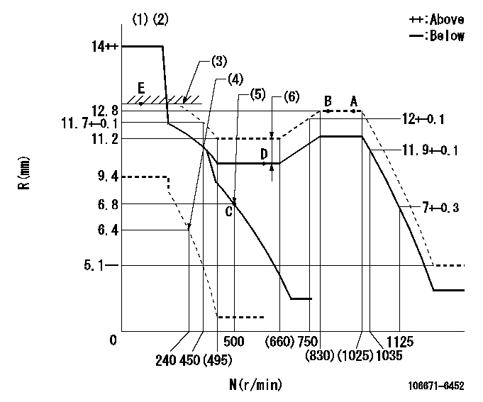
N:Pump speed
R:Rack position (mm)
(1)Target notch: K
(2)Tolerance for racks not indicated: +-0.05mm.
(3)RACK LIMIT
(4)Set idle sub-spring
(5)Main spring setting
(6)Boost compensator stroke: BCL
----------
K=12 BCL=0.4+-0.1mm
----------
----------
K=12 BCL=0.4+-0.1mm
----------
Speed control lever angle
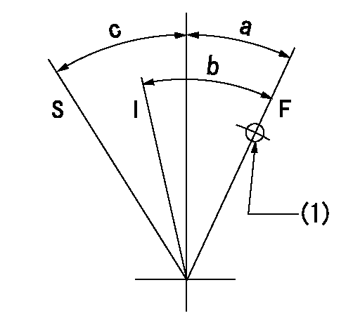
F:Full speed
I:Idle
S:Stop
(1)Use the hole at R = aa
----------
aa=70mm
----------
a=3deg+-5deg b=18deg+-5deg c=31deg+-3deg
----------
aa=70mm
----------
a=3deg+-5deg b=18deg+-5deg c=31deg+-3deg
Stop lever angle
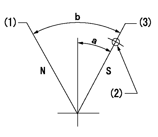
N:Pump normal
S:Stop the pump.
(1)Normal
(2)Use the hole at R = aa
(3)Rack position bb, pump speed cc (seal at delivery)
----------
aa=23mm bb=1-0.5mm cc=0r/min
----------
a=15deg+-5deg b=70deg+-5deg
----------
aa=23mm bb=1-0.5mm cc=0r/min
----------
a=15deg+-5deg b=70deg+-5deg
0000001501 TAMPER PROOF

Tamperproofing-equipped boost compensator cover installation procedure
(A) After adjusting the boost compensator, tighten the bolts to remove the heads.
(1)Before adjusting the governor and the boost compensator, tighten the screw to the specified torque.
(Tightening torque T = T1 maximum)
(2)After adjusting the governor and the boost compensator, tighten to the specified torque to break off the bolt heads.
(Tightening torque T = T2)
----------
T1=2.5N-m(0.25kgf-m) T2=2.9~4.4N-m(0.3~0.45kgf-m)
----------
----------
T1=2.5N-m(0.25kgf-m) T2=2.9~4.4N-m(0.3~0.45kgf-m)
----------
Timing setting

(1)Pump vertical direction
(2)Position of timer's threaded installation hole at No 1 cylinder's beginning of injection
(3)B.T.D.C.: aa
(4)-
----------
aa=9deg
----------
a=(50deg)
----------
aa=9deg
----------
a=(50deg)
Information:
Illustration 1 g00564355
7W-2743 Electronic Speed Switch (ESS)
(1) Push button for Overspeed Verification
(2) Reset button
(3) Overspeed indicator lamp
(4) Seal screw plug for adjusting the engine overspeed
(5) Seal screw plug for adjusting the crank terminate speed
(6) Seal screw plug for adjusting the oil step pressure speed setting The procedure for the magnetic pickup test will determine if the operation of the magnetic pickup is correct.
Connect a 6V-7070 Digital Multimeter to the "COM" terminal and the "SIG" terminal. The terminals are (ESS-3)and (ESS-4) of the ESS. Set the meter voltage scale to a scale that is greater than 1.5 VAC. Start the engine. Run the engine at low idle or 600 rpm. Choose the one that is larger. If the voltage that is measured is 1.5 VAC or more, the operation of the magnetic pickup is correct. If the voltage is less than 1.5 VAC, go to Step 2.
Stop the engine. Disconnect the wiring for the magnetic pickup at the plug-in connector. Connect the voltmeter to the connector terminals of the magnetic pickup. Start the engine. Run the engine at low idle or 600 rpm. Choose the one that is larger. If the voltage that is measured is 1.5 VAC or more, repair the wiring that is between the magnetic pickup and the ESS. If the voltage is less than 1.5 VAC, go to Step 3.
Illustration 2 g00564913
Magnetic pickup
(1) Clearance
(2) Magnetic pickup
(3) Wires to the connector
(4) Locknut
(5) Flywheel housing
(6) Ring gear
Loosen locknut (4) and turn magnetic pickup (2) in the counterclockwise direction in order to remove magnetic pickup (2) from flywheel housing (5). Turn the flywheel until a gear tooth of ring gear (6) is directly in the center of the threaded hole for magnetic pickup (2). Install magnetic pickup (2) in flywheel housing (5).
Turn magnetic pickup (2) in the clockwise direction until the end of magnetic pickup (2) slightly touches the gear tooth. Turn the magnetic pickup for one-half turn in the counterclockwise direction in order to set correct clearance (1). Tighten locknut (4) to a torque of 45 7 N m (33 5 lb ft). Note: Do not allow the magnetic pickup to turn while the locknut is tightened.
Repeat Step 2. If the voltage is still less than 1.5 VAC, replace the magnetic pickup.
Have questions with 106671-6452?
Group cross 106671-6452 ZEXEL
Isuzu
Isuzu
106671-6452
9 400 613 008
1156033342
INJECTION-PUMP ASSEMBLY
6HK1-XQA
6HK1-XQA