Information injection-pump assembly
BOSCH
9 400 612 221
9400612221
ZEXEL
106671-6401
1066716401

Rating:
Service parts 106671-6401 INJECTION-PUMP ASSEMBLY:
1.
_
7.
COUPLING PLATE
8.
_
9.
_
11.
Nozzle and Holder
1-15300-403-0
12.
Open Pre:MPa(Kqf/cm2)
19.6{200}
15.
NOZZLE SET
Include in #1:
106671-6401
as INJECTION-PUMP ASSEMBLY
Cross reference number
BOSCH
9 400 612 221
9400612221
ZEXEL
106671-6401
1066716401
Zexel num
Bosch num
Firm num
Name
Calibration Data:
Adjustment conditions
Test oil
1404 Test oil ISO4113 or {SAEJ967d}
1404 Test oil ISO4113 or {SAEJ967d}
Test oil temperature
degC
40
40
45
Nozzle and nozzle holder
105780-8130
Bosch type code
EFEP215A
Nozzle
105780-0050
Bosch type code
DN6TD119NP1T
Nozzle holder
105780-2090
Bosch type code
EFEP215
Opening pressure
MPa
17.2
Opening pressure
kgf/cm2
175
Injection pipe
Outer diameter - inner diameter - length (mm) mm 8-3-600
Outer diameter - inner diameter - length (mm) mm 8-3-600
Overflow valve
134424-3920
Overflow valve opening pressure
kPa
127
107
147
Overflow valve opening pressure
kgf/cm2
1.3
1.1
1.5
Tester oil delivery pressure
kPa
157
157
157
Tester oil delivery pressure
kgf/cm2
1.6
1.6
1.6
Direction of rotation (viewed from drive side)
Right R
Right R
Injection timing adjustment
Direction of rotation (viewed from drive side)
Right R
Right R
Injection order
1-4-2-6-
3-5
Pre-stroke
mm
4.2
4.15
4.25
Beginning of injection position
Drive side NO.1
Drive side NO.1
Difference between angles 1
Cal 1-4 deg. 60 59.5 60.5
Cal 1-4 deg. 60 59.5 60.5
Difference between angles 2
Cyl.1-2 deg. 120 119.5 120.5
Cyl.1-2 deg. 120 119.5 120.5
Difference between angles 3
Cal 1-6 deg. 180 179.5 180.5
Cal 1-6 deg. 180 179.5 180.5
Difference between angles 4
Cal 1-3 deg. 240 239.5 240.5
Cal 1-3 deg. 240 239.5 240.5
Difference between angles 5
Cal 1-5 deg. 300 299.5 300.5
Cal 1-5 deg. 300 299.5 300.5
Injection quantity adjustment
Adjusting point
A
Rack position
10.1
Pump speed
r/min
1050
1050
1050
Average injection quantity
mm3/st.
481
478
484
Max. variation between cylinders
%
0
-3
3
Basic
*
Fixing the lever
*
Boost pressure
kPa
173
173
Boost pressure
mmHg
1300
1300
Injection quantity adjustment_02
Adjusting point
B
Rack position
4.2+-0.5
Pump speed
r/min
305
305
305
Average injection quantity
mm3/st.
15
13
17
Max. variation between cylinders
%
0
-13
13
Fixing the rack
*
Boost pressure
kPa
0
0
0
Boost pressure
mmHg
0
0
0
Injection quantity adjustment_03
Adjusting point
C
Rack position
7.3+-0.1
Pump speed
r/min
500
500
500
Average injection quantity
mm3/st.
230
227
233
Fixing the lever
*
Boost pressure
kPa
0
0
0
Boost pressure
mmHg
0
0
0
Boost compensator adjustment
Pump speed
r/min
500
500
500
Rack position
7.3+-0.1
Boost pressure
kPa
53.3
50.6
56
Boost pressure
mmHg
400
380
420
Boost compensator adjustment_02
Pump speed
r/min
500
500
500
Rack position
(10.1)
Boost pressure
kPa
160
160
160
Boost pressure
mmHg
1200
1200
1200
Timer adjustment
Pump speed
r/min
1050++
Advance angle
deg.
0
0
0
Remarks
Do not advance until starting N = 1050.
Do not advance until starting N = 1050.
Timer adjustment_02
Pump speed
r/min
-
Advance angle
deg.
1
1
1
Remarks
Measure the actual speed, stop
Measure the actual speed, stop
Test data Ex:
Governor adjustment
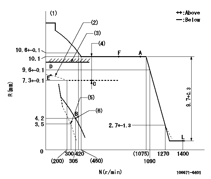
N:Pump speed
R:Rack position (mm)
(1)Tolerance for racks not indicated: +-0.05mm.
(2)May not protrude at starting.
(3)Boost compensator excessive fuel lever setting: L1 (at boost pressure 0)
(4)Boost compensator stroke: BCL
(5)Set idle sub-spring
(6)Main spring setting
----------
L1=9.3+-0.1mm BCL=(2.8)mm
----------
----------
L1=9.3+-0.1mm BCL=(2.8)mm
----------
Speed control lever angle
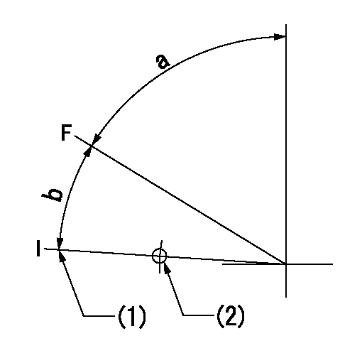
F:Full speed
I:Idle
(1)Stopper bolt setting
(2)Use the hole at R = aa
----------
aa=135mm
----------
a=72deg+-5deg b=13deg+-5deg
----------
aa=135mm
----------
a=72deg+-5deg b=13deg+-5deg
0000000901
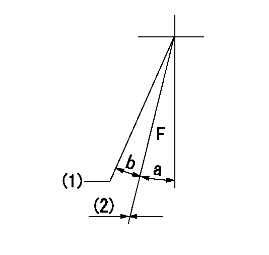
F:Full load
(1)Set the tamper proofing.
(2)Fix using the stopper bolt.
----------
----------
a=18deg+-5deg b=(2.5deg)
----------
----------
a=18deg+-5deg b=(2.5deg)
Stop lever angle

N:Pump normal
S:Stop the pump.
(1)Drive side
----------
----------
a=32deg+-5deg b=64deg+-5deg
----------
----------
a=32deg+-5deg b=64deg+-5deg
0000001101
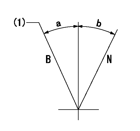
N:Normal
B:When boosted
(1)Rack position = aa at boost pressure 0.
----------
aa=9.3+-0.1mm
----------
a=(8deg) b=(15deg)
----------
aa=9.3+-0.1mm
----------
a=(8deg) b=(15deg)
0000001501 TAMPER PROOF
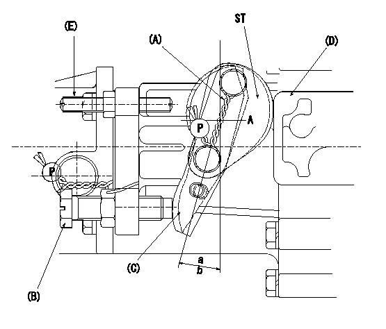
(A): sealing wire
(B): full load stopper bolt
(C): load lever
(D): governor cover boss
(E): tamper lever installation bolt
ST:Sealing
a, b: load lever angle
1. Method for setting tamperproof proofing
(1)After completing governor adjustment, install lever marked A when the load lever (C)'s angle is equal to or greater than a but less than b, and lever marked B when angle is equal to or greater than c but equal to or less than d (as shown in figure).
Sealing A: PN1
Sealing B: PN2
(2)At R1 and N1 loosen bolt B until the lever installed in (1) contacts the governor cover boss.
(3)Confirm that the rack position at this time is R = R2 or less.
(4)After this, readjust the full rack position using the load lever C.
(5)Seal bolt E.
----------
a=13deg b=18deg c=18deg d=23deg PN1=154386-3300 PN2=154386-3400 R1=L R2=(1.4)mm N1=1400r/min
----------
----------
a=13deg b=18deg c=18deg d=23deg PN1=154386-3300 PN2=154386-3400 R1=L R2=(1.4)mm N1=1400r/min
----------
Timing setting

(1)Pump vertical direction
(2)Position of timer's threaded hole at No 1 cylinder's beginning of injection
(3)B.T.D.C.: aa
(4)-
----------
aa=18deg
----------
a=(70deg)
----------
aa=18deg
----------
a=(70deg)
Information:
Fuel Tank Drain
Fuel tank drains are used to drain water and sediment from the fuel tank daily. The drain must be located on the lowest part of the fuel tank where the containments collect.Note: Daily draining of water and sediment from the fuel tank has been a standard maintenance requirement for decades.Advanced Tank Breather Filter
Preventing short fuel system life by keeping dust from entering the fuel tank.Water Separators
Water separators are required to remove large quantities of latent water from the fuel.Primary Fuel Filters
Primary fuel filters are required to remove large abrasives from the fuel supply and prevent premature clogging of the 4-micron secondary filters from excessive debris.Secondary Fuel Filters
Series filtration more than doubles wear life over single filtration.Electronic Unit Injectors (EUI)
An adequate fuel supply pressure is essential to prevent cavitation of internal injector components due to incomplete fuel fill.Major Factors Which Negatively Affect Fuel System Wear
Abrasive Contaminants
Increased injection pressure acting on the same level of abrasive contaminants in the fuel results in accelerated injector abrasive wear. This abrasive wear cannot be eliminated by using improved materials or processes. Abrasive wear only can be reduced by removing abrasives from the fuel. Solution
Single or series High Efficiency fuel filters and/or bulk fuel filter/water coalescer.Water in Fuel
An excessive amount of latent water in the fuel is a key cause of injector failure. Water has inadequate film strength to prevent metal-to-metal contact between the plunger and barrel, resulting in plunger scuffing or seizure. Water can be effectively by the use and regular maintenance of a water separator or bulk fuel filter/water coalescer. Removal of excess latent water is essential to prevent scuffing with the upcoming injection pressure increases and subsequent hydraulic loading of internal injector parts.Solution
Proper maintenance of fuel tank drains, water separators and/or use of a bulk fuel filter/water coalescer.Excessive Fuel Temperature
Increasing fuel temperatures reduces fuel viscosity and resultant fuel film strength. Reduced film strength increases the probability of injector plunger and barrel scuffing or seizure. Limiting the maximum fuel temperature will become even more critical with the increase of use if low sulfur fuel which has a lower film strength and common rail fuel systems which run elevated fuel temperatures. Fuel temperatures also play in diesel and biodiesel fuel degradation.Solution
Properly maintain fuel filters and fuel coolers where needed. Ensure proper consideration for materials used in fuel coolers as zinc, copper, lead, and tin can have adverse effects on fuel degradation.Customer Maintenance Practices
Fuel system performance, sophistication, and complexity continue to increase at a rapid pace. It is more important than ever for the user to maintain fuel filters in order to prevent filter restriction and the problems caused by low fuel pressure. It is also important to use quality Advanced Efficiency filters in order to trap and hold microscopic abrasive debris, which causes accelerated wear in modern fuel systems.C7 and C9 HEUI Fuel System Diagram
Note: The following illustration identifies components that may be included in many different arrangements. Refer to the Service Information System (SIS) for the correct components for the