Information injection-pump assembly
BOSCH
9 400 611 453
9400611453
ZEXEL
106671-6400
1066716400
ISUZU
1156032770
1156032770
Rating:
Service parts 106671-6400 INJECTION-PUMP ASSEMBLY:
1.
_
6.
COUPLING PLATE
7.
COUPLING PLATE
8.
_
9.
_
11.
Nozzle and Holder
1-15300-303-2
12.
Open Pre:MPa(Kqf/cm2)
19.6{200}
15.
NOZZLE SET
Include in #1:
106671-6400
as INJECTION-PUMP ASSEMBLY
Cross reference number
BOSCH
9 400 611 453
9400611453
ZEXEL
106671-6400
1066716400
ISUZU
1156032770
1156032770
Zexel num
Bosch num
Firm num
Name
9 400 611 453
1156032770 ISUZU
INJECTION-PUMP ASSEMBLY
6RB1-MTC * K 14CA PE6P,6PD PE
6RB1-MTC * K 14CA PE6P,6PD PE
Calibration Data:
Adjustment conditions
Test oil
1404 Test oil ISO4113 or {SAEJ967d}
1404 Test oil ISO4113 or {SAEJ967d}
Test oil temperature
degC
40
40
45
Nozzle and nozzle holder
105780-8130
Bosch type code
EFEP215A
Nozzle
105780-0050
Bosch type code
DN6TD119NP1T
Nozzle holder
105780-2090
Bosch type code
EFEP215
Opening pressure
MPa
17.2
Opening pressure
kgf/cm2
175
Injection pipe
Outer diameter - inner diameter - length (mm) mm 8-3-600
Outer diameter - inner diameter - length (mm) mm 8-3-600
Overflow valve
134424-3920
Overflow valve opening pressure
kPa
127
107
147
Overflow valve opening pressure
kgf/cm2
1.3
1.1
1.5
Tester oil delivery pressure
kPa
157
157
157
Tester oil delivery pressure
kgf/cm2
1.6
1.6
1.6
Direction of rotation (viewed from drive side)
Right R
Right R
Injection timing adjustment
Direction of rotation (viewed from drive side)
Right R
Right R
Injection order
1-4-2-6-
3-5
Pre-stroke
mm
4.2
4.15
4.25
Beginning of injection position
Drive side NO.1
Drive side NO.1
Difference between angles 1
Cal 1-4 deg. 60 59.5 60.5
Cal 1-4 deg. 60 59.5 60.5
Difference between angles 2
Cyl.1-2 deg. 120 119.5 120.5
Cyl.1-2 deg. 120 119.5 120.5
Difference between angles 3
Cal 1-6 deg. 180 179.5 180.5
Cal 1-6 deg. 180 179.5 180.5
Difference between angles 4
Cal 1-3 deg. 240 239.5 240.5
Cal 1-3 deg. 240 239.5 240.5
Difference between angles 5
Cal 1-5 deg. 300 299.5 300.5
Cal 1-5 deg. 300 299.5 300.5
Injection quantity adjustment
Adjusting point
A
Rack position
11.5
Pump speed
r/min
1000
1000
1000
Average injection quantity
mm3/st.
412
409
415
Max. variation between cylinders
%
0
-3
3
Basic
*
Fixing the lever
*
Boost pressure
kPa
140
140
Boost pressure
mmHg
1050
1050
Injection quantity adjustment_02
Adjusting point
-
Rack position
4.5+-0.5
Pump speed
r/min
305
305
305
Average injection quantity
mm3/st.
15.5
12.3
18.7
Max. variation between cylinders
%
0
-13
13
Fixing the rack
*
Boost pressure
kPa
0
0
0
Boost pressure
mmHg
0
0
0
Remarks
Adjust only variation between cylinders; adjust governor according to governor specifications.
Adjust only variation between cylinders; adjust governor according to governor specifications.
Injection quantity adjustment_03
Adjusting point
C
Rack position
7.9
Pump speed
r/min
500
500
500
Average injection quantity
mm3/st.
207
201
213
Fixing the lever
*
Boost pressure
kPa
0
0
0
Boost pressure
mmHg
0
0
0
Boost compensator adjustment
Pump speed
r/min
500
500
500
Rack position
7.9
Boost pressure
kPa
22
20.7
23.3
Boost pressure
mmHg
165
155
175
Boost compensator adjustment_02
Pump speed
r/min
500
500
500
Rack position
(11.5)
Boost pressure
kPa
127
127
127
Boost pressure
mmHg
950
950
950
Timer adjustment
Pump speed
r/min
1050++
Advance angle
deg.
0
0
0
Remarks
Do not advance until starting N = 1050.
Do not advance until starting N = 1050.
Timer adjustment_02
Pump speed
r/min
-
Advance angle
deg.
1
1
1
Remarks
Measure the actual speed, stop
Measure the actual speed, stop
Test data Ex:
Governor adjustment
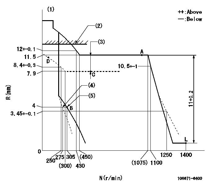
N:Pump speed
R:Rack position (mm)
(1)Tolerance for racks not indicated: +-0.05mm.
(2)Boost compensator excessive fuel lever setting: L1 (at boost pressure 0)
(3)Boost compensator stroke: BCL
(4)Set idle sub-spring
(5)Main spring setting
----------
L1=12.5+-0.1mm BCL=(3.6)+-0.1mm
----------
----------
L1=12.5+-0.1mm BCL=(3.6)+-0.1mm
----------
Speed control lever angle
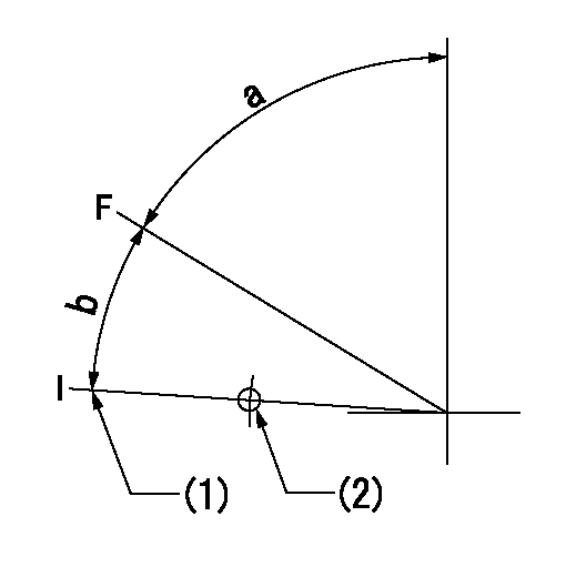
F:Full speed
I:Idle
(1)Stopper bolt setting
(2)Use the hole at R = aa
----------
aa=135mm
----------
a=(74deg)+-5deg b=14deg+-5deg
----------
aa=135mm
----------
a=(74deg)+-5deg b=14deg+-5deg
0000000901
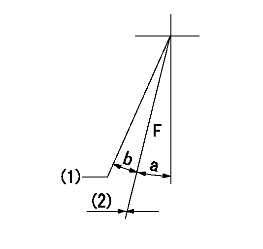
F:Full load
(1)Set the tamper proofing.
(2)Fix using the stopper bolt.
----------
----------
a=16deg+-5deg b=(2.5deg)
----------
----------
a=16deg+-5deg b=(2.5deg)
Stop lever angle

N:Pump normal
S:Stop the pump.
(1)Drive side
----------
----------
a=32deg+-5deg b=64deg+-5deg
----------
----------
a=32deg+-5deg b=64deg+-5deg
0000001101
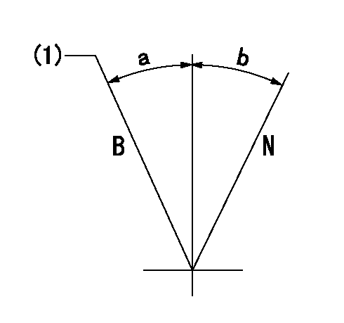
N:Normal
B:When boosted
(1)Rack position = aa at boost pressure 0.
----------
aa=12.5+-0.1mm
----------
a=(15deg) b=(15deg)
----------
aa=12.5+-0.1mm
----------
a=(15deg) b=(15deg)
0000001501 TAMPER PROOF
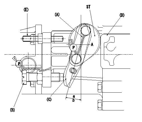
(A): sealing wire
(B): full load stopper bolt
(C): load lever
(D): governor cover boss
(E): tamper lever installation bolt
ST:Sealing
a, b: load lever angle
1. Method for setting tamperproof proofing
(1)After completing governor adjustment, install lever marked A when the load lever (C)'s angle is equal to or greater than a but less than b, and lever marked B when angle is equal to or greater than c but equal to or less than d (as shown in figure).
Sealing A: PN1
Sealing B: PN2
(2)At R1 and N1 loosen bolt B until the lever installed in (1) contacts the governor cover boss.
(3)Confirm that the rack position at this time is R = R2 or less.
(4)After this, readjust the full rack position using the load lever C.
(5)Seal bolt E.
----------
a=11deg b=16deg c=16deg d=21deg PN1=154386-3300 PN2=154386-3400 R1=L R2=2mm N1=1400r/min
----------
----------
a=11deg b=16deg c=16deg d=21deg PN1=154386-3300 PN2=154386-3400 R1=L R2=2mm N1=1400r/min
----------
Timing setting

(1)Pump vertical direction
(2)Position of timer's threaded hole at No 1 cylinder's beginning of injection
(3)B.T.D.C.: aa
(4)-
----------
aa=15deg
----------
a=(70deg)
----------
aa=15deg
----------
a=(70deg)
Information:
Illustration 17 g03389921
Illustration 18 g03389931
Read the warning and select "Accept" to continue.
Illustration 19 g03389947
Once the reset is completed, a log of the reset is captured and visible as a new row of information in the Diesel Oxidation Catalyst Replacement screen. Selective Catalytic Reduction (SCR) Maintenance on Tier 4 Final Products
Note: Refer to Table 5 for the existing SCR catalyst part number being serviced along with the corresponding new service kit, and the clamp part number required for reassembly.
Table 5
SCR Part Number Service Kit Part Number Required Clamp Part Number
447-8145 N/A 346-0335
447-8143 N/A 346-0335
447-8141 N/A 346-0335
447-8149 N/A 346-0335
447-8147 N/A 346-0335
447-8163 N/A 346-0335
447-8151 N/A 346-0335
375-0989 N/A 346-0335
447-8165 N/A 346-0335
447-8153 N/A 346-0335
447-8161 N/A 346-0335
447-8159 N/A 346-0335
447-8157 N/A 346-0335
447-8169 N/A 346-0335
447-8173 N/A 346-0335
447-8171 N/A 346-0335
447-8167 N/A 346-0335
447-8175 N/A 346-0335 The Aftertreatment SCR Catalyst Replacement procedure must be performed when the SCR Catalyst has been replaced. This is necessary to ensure that the engine meets emissions requirements. Follow the procedure below to reset the SCR Catalyst model in the aftertreatment software.
Connect to Cat® ET.
Illustration 20 g03390636
Connect to "Engine #1 Aftertreatment Controller".
Illustration 21 g03740190
Select "Service" from the top menu and select "Service Procedures".
Illustration 22 g03740205
Select "Aftertreatment #1 SCR Catalyst Replacement" and select "Start".
Illustration 23 g03740210
Select "Reset".
Illustration 24 g03740216
You must read the warning and select "Accept" to continue.
Enter the factory passwords to continue.
Illustration 25 g03740230
Once the reset is completed, a log of the reset is captured and visible as a new row of information in the "Aftertreatment #1 SCR Catalyst Replacement" screen.