Information injection-pump assembly
ZEXEL
106671-6292
1066716292
ISUZU
1156032173
1156032173

Rating:
Service parts 106671-6292 INJECTION-PUMP ASSEMBLY:
1.
_
7.
COUPLING PLATE
8.
_
9.
_
11.
Nozzle and Holder
1-15300-332-0
12.
Open Pre:MPa(Kqf/cm2)
17.7{180}/22.1{225}
 BASCOLIN Original Nozzles DLLA152SM070 105025-0700 9 432 611 546")
15.
NOZZLE SET
Include in #1:
106671-6292
as INJECTION-PUMP ASSEMBLY
Cross reference number
ZEXEL
106671-6292
1066716292
ISUZU
1156032173
1156032173
Zexel num
Bosch num
Firm num
Name
Calibration Data:
Adjustment conditions
Test oil
1404 Test oil ISO4113 or {SAEJ967d}
1404 Test oil ISO4113 or {SAEJ967d}
Test oil temperature
degC
40
40
45
Nozzle and nozzle holder
105780-8140
Bosch type code
EF8511/9A
Nozzle
105780-0000
Bosch type code
DN12SD12T
Nozzle holder
105780-2080
Bosch type code
EF8511/9
Opening pressure
MPa
17.2
Opening pressure
kgf/cm2
175
Injection pipe
Outer diameter - inner diameter - length (mm) mm 8-3-600
Outer diameter - inner diameter - length (mm) mm 8-3-600
Overflow valve
131424-8620
Overflow valve opening pressure
kPa
206
172
240
Overflow valve opening pressure
kgf/cm2
2.1
1.75
2.45
Tester oil delivery pressure
kPa
157
157
157
Tester oil delivery pressure
kgf/cm2
1.6
1.6
1.6
Direction of rotation (viewed from drive side)
Left L
Left L
Injection timing adjustment
Direction of rotation (viewed from drive side)
Left L
Left L
Injection order
1-5-3-6-
2-4
Pre-stroke
mm
4.5
4.47
4.53
Beginning of injection position
Governor side NO.1
Governor side NO.1
Difference between angles 1
Cal 1-5 deg. 60 59.75 60.25
Cal 1-5 deg. 60 59.75 60.25
Difference between angles 2
Cal 1-3 deg. 120 119.75 120.25
Cal 1-3 deg. 120 119.75 120.25
Difference between angles 3
Cal 1-6 deg. 180 179.75 180.25
Cal 1-6 deg. 180 179.75 180.25
Difference between angles 4
Cyl.1-2 deg. 240 239.75 240.25
Cyl.1-2 deg. 240 239.75 240.25
Difference between angles 5
Cal 1-4 deg. 300 299.75 300.25
Cal 1-4 deg. 300 299.75 300.25
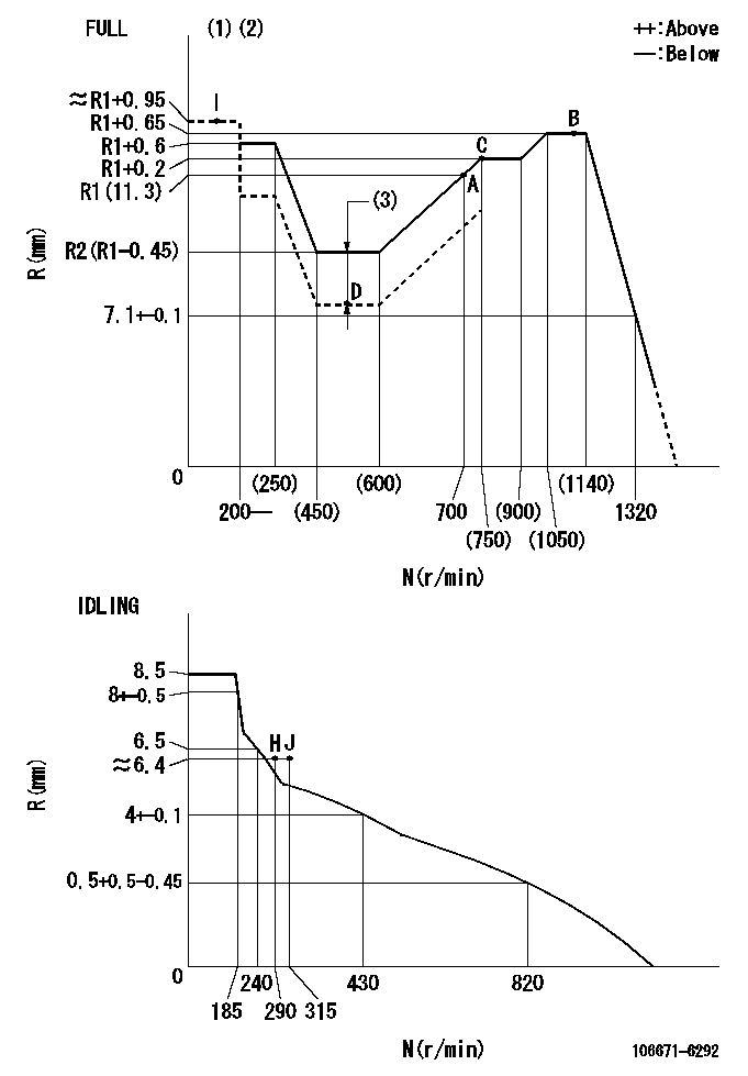
Injection quantity adjustment
Adjusting point
-
Rack position
11.3
Pump speed
r/min
700
700
700
Average injection quantity
mm3/st.
149
147
151
Max. variation between cylinders
%
0
-3
3
Basic
*
Fixing the rack
*
Standard for adjustment of the maximum variation between cylinders
*
Injection quantity adjustment_02
Adjusting point
H
Rack position
6.4+-0.5
Pump speed
r/min
290
290
290
Average injection quantity
mm3/st.
10
6.8
13.2
Max. variation between cylinders
%
0
-13
13
Fixing the rack
*
Standard for adjustment of the maximum variation between cylinders
*
Injection quantity adjustment_03
Adjusting point
A
Rack position
R1(11.3)
Pump speed
r/min
700
700
700
Average injection quantity
mm3/st.
149
147
151
Basic
*
Fixing the lever
*
Boost pressure
kPa
60
60
Boost pressure
mmHg
450
450
Injection quantity adjustment_04
Adjusting point
B
Rack position
R1+0.65
Pump speed
r/min
1100
1100
1100
Average injection quantity
mm3/st.
161
155
167
Fixing the lever
*
Boost pressure
kPa
60
60
Boost pressure
mmHg
450
450
Boost compensator adjustment
Pump speed
r/min
500
500
500
Rack position
R2-1.75
Boost pressure
kPa
4
4
6.7
Boost pressure
mmHg
30
30
50
Boost compensator adjustment_02
Pump speed
r/min
500
500
500
Rack position
R2(R1-0.
45)
Boost pressure
kPa
46.7
46.7
46.7
Boost pressure
mmHg
350
350
350
Timer adjustment
Pump speed
r/min
850--
Advance angle
deg.
0
0
0
Remarks
Start
Start
Timer adjustment_02
Pump speed
r/min
800
Advance angle
deg.
0.5
Timer adjustment_03
Pump speed
r/min
875
Advance angle
deg.
1.5
1
2
Remarks
Finish
Finish
Test data Ex:
Governor adjustment
N:Pump speed
R:Rack position (mm)
(1)Torque cam stamping: T1
(2)Tolerance for racks not indicated: +-0.05mm.
(3)Boost compensator stroke: BCL
----------
T1=AE45 BCL=1.75+-0.1mm
----------
----------
T1=AE45 BCL=1.75+-0.1mm
----------
Speed control lever angle
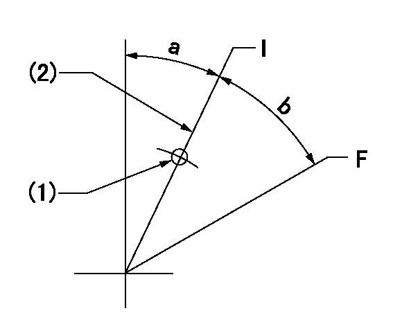
F:Full speed
I:Idle
(1)Use the pin at R = aa
(2)Stopper bolt set position 'H'
----------
aa=35mm
----------
a=27deg+-5deg b=32.5deg+-3deg
----------
aa=35mm
----------
a=27deg+-5deg b=32.5deg+-3deg
Stop lever angle
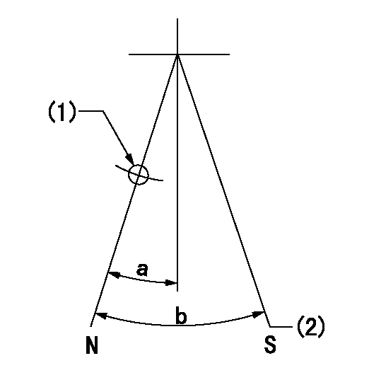
N:Pump normal
S:Stop the pump.
(1)Use the pin at R = aa
(2)Set the stopper bolt so that speed = bb and rack position = cc. (Confirm non-injection.)
----------
aa=40mm bb=0r/min cc=1.5+-0.3mm
----------
a=22deg+-5deg b=41deg+-5deg
----------
aa=40mm bb=0r/min cc=1.5+-0.3mm
----------
a=22deg+-5deg b=41deg+-5deg
Timing setting

(1)Pump vertical direction
(2)Position of timer's threaded hole at No 1 cylinder's beginning of injection
(3)B.T.D.C.: aa
(4)-
----------
aa=10deg
----------
a=(40deg)
----------
aa=10deg
----------
a=(40deg)
Information:
ACTION REQUIRED
Do not order the 601-8546 and 601-8547 Hoses. The new hoses have been direct shipped to the dealership prior to the release of this Service Letter program.
If you have not received the parts, the parts received are damaged, or if you have any questions you will need to work with your Dealer TC to submit the information or question through CPI Feedback within the Service Information Management System (SIMSi).
Give the information to your Dealer Technical Communicator (TC) along with this service letter program number and CPI number 472555.
Request the Dealer TC to submit the CPI Feedback.
Refer to the attached Rework Procedure.
OWNER NOTIFICATION
Owners in the following countries will receive the attached Owner Notification:
US
Canada
SERVICE CLAIM ALLOWANCES
Caterpillar Dealer Suggested Customer Suggested
Parts % Labor Hrs% Parts % Labor Hrs% Parts % Labor Hrs%
100% 100% 0% 0% 0% 0%
This is a 1.5-hour job
Note: $60 US Dollars are allowed for 10 Liters of coolant.
PARTS DISPOSITION
Handle the parts in accordance with your Warranty Bulletin on warranty parts handling.
MAKE EVERY EFFORT TO COMPLETE THIS PROGRAM AS SOON AS POSSIBLE.
EXAMPLE COPY OF OWNER NOTIFICATION
XYZ Corporation
3240 Arrow Drive
Anywhere, YZ 99999
PRIORITY - PRODUCT IMPROVEMENT PROGRAM FOR REPLACING THE DEF INJECTOR COOLANT HOSES
MODELS INVOLVED - CERTAIN 313 AND 315 NGH EXCAVATORS
Dear Cat Product Owner:
The existing coolant hoses need to be replaced on the products listed below. The existing hoses can leak water and/or burst. You will not be charged for the service performed.
Contact your local Cat dealer immediately to schedule this service. The dealer will advise you of the time required to complete this service.
If you are no longer the owner of this product(s), please contact your local Cat dealer so that our records can be updated. Please refer the dealer to their Service Letter dated 01Jul2020 when scheduling this service.
We regret the inconvenience this may cause you, and urge you to have this service performed as soon as possible to prevent unscheduled downtime.
Caterpillar Inc.
Identification #(s)
Attached to 01Jul2020 Service Letter
Rework Procedure
1. Confirm the machine/engine components/coolant are cooled down for safety.
2. Drain coolant (approximately 10L) to avoid spilling out from hoses during replacement.
3. Removed the strap on hose. Refer to Image1.3.1.
Image1.3.1
4. Loosen the clamps and remove the hoses (both inlet and outlet). Refer to Image1.4.1.
Image1.4.1
5. Install new parts. Refer to Images1.5.1 and 1.5.2.
Image1.5.1
Image1.5.2
6. Fill the coolant and check for leakage from the hoses.