Information injection-pump assembly
ZEXEL
106671-6272
1066716272
ISUZU
1156032153
1156032153

Rating:
Service parts 106671-6272 INJECTION-PUMP ASSEMBLY:
1.
_
7.
COUPLING PLATE
8.
_
9.
_
11.
Nozzle and Holder
1-15300-332-0
12.
Open Pre:MPa(Kqf/cm2)
17.7{180}/22.1{225}
 BASCOLIN Original Nozzles DLLA152SM070 105025-0700 9 432 611 546")
15.
NOZZLE SET
Include in #1:
106671-6272
as INJECTION-PUMP ASSEMBLY
Cross reference number
ZEXEL
106671-6272
1066716272
ISUZU
1156032153
1156032153
Zexel num
Bosch num
Firm num
Name
Calibration Data:
Adjustment conditions
Test oil
1404 Test oil ISO4113 or {SAEJ967d}
1404 Test oil ISO4113 or {SAEJ967d}
Test oil temperature
degC
40
40
45
Nozzle and nozzle holder
105780-8140
Bosch type code
EF8511/9A
Nozzle
105780-0000
Bosch type code
DN12SD12T
Nozzle holder
105780-2080
Bosch type code
EF8511/9
Opening pressure
MPa
17.2
Opening pressure
kgf/cm2
175
Injection pipe
Outer diameter - inner diameter - length (mm) mm 8-3-600
Outer diameter - inner diameter - length (mm) mm 8-3-600
Overflow valve
131424-8620
Overflow valve opening pressure
kPa
206
172
240
Overflow valve opening pressure
kgf/cm2
2.1
1.75
2.45
Tester oil delivery pressure
kPa
157
157
157
Tester oil delivery pressure
kgf/cm2
1.6
1.6
1.6
Direction of rotation (viewed from drive side)
Left L
Left L
Injection timing adjustment
Direction of rotation (viewed from drive side)
Left L
Left L
Injection order
1-5-3-6-
2-4
Pre-stroke
mm
4.5
4.47
4.53
Beginning of injection position
Governor side NO.1
Governor side NO.1
Difference between angles 1
Cal 1-5 deg. 60 59.75 60.25
Cal 1-5 deg. 60 59.75 60.25
Difference between angles 2
Cal 1-3 deg. 120 119.75 120.25
Cal 1-3 deg. 120 119.75 120.25
Difference between angles 3
Cal 1-6 deg. 180 179.75 180.25
Cal 1-6 deg. 180 179.75 180.25
Difference between angles 4
Cyl.1-2 deg. 240 239.75 240.25
Cyl.1-2 deg. 240 239.75 240.25
Difference between angles 5
Cal 1-4 deg. 300 299.75 300.25
Cal 1-4 deg. 300 299.75 300.25
Injection quantity adjustment
Adjusting point
-
Rack position
11.3
Pump speed
r/min
700
700
700
Average injection quantity
mm3/st.
149
147
151
Max. variation between cylinders
%
0
-3
3
Basic
*
Fixing the rack
*
Standard for adjustment of the maximum variation between cylinders
*
Injection quantity adjustment_02
Adjusting point
H
Rack position
6.4+-0.5
Pump speed
r/min
290
290
290
Average injection quantity
mm3/st.
10
6.8
13.2
Max. variation between cylinders
%
0
-13
13
Fixing the rack
*
Standard for adjustment of the maximum variation between cylinders
*
Injection quantity adjustment_03
Adjusting point
A
Rack position
R1(11.3)
Pump speed
r/min
700
700
700
Average injection quantity
mm3/st.
149
147
151
Basic
*
Fixing the lever
*
Boost pressure
kPa
60
60
Boost pressure
mmHg
450
450
Injection quantity adjustment_04
Adjusting point
B
Rack position
R1+0.65
Pump speed
r/min
1100
1100
1100
Average injection quantity
mm3/st.
161
155
167
Fixing the lever
*
Boost pressure
kPa
60
60
Boost pressure
mmHg
450
450
Injection quantity adjustment_05
Adjusting point
E
Rack position
R1+0.2
Pump speed
r/min
800
800
800
Average injection quantity
mm3/st.
149
143
155
Fixing the lever
*
Boost pressure
kPa
60
60
Boost pressure
mmHg
450
450
Boost compensator adjustment
Pump speed
r/min
500
500
500
Rack position
R2-1.75
Boost pressure
kPa
4
4
6.7
Boost pressure
mmHg
30
30
50
Boost compensator adjustment_02
Pump speed
r/min
500
500
500
Rack position
R2(R1-0.
45)
Boost pressure
kPa
46.7
46.7
46.7
Boost pressure
mmHg
350
350
350
Timer adjustment
Pump speed
r/min
850--
Advance angle
deg.
0
0
0
Remarks
Start
Start
Timer adjustment_02
Pump speed
r/min
800
Advance angle
deg.
0.5
Timer adjustment_03
Pump speed
r/min
875
Advance angle
deg.
1.5
1
2
Remarks
Finish
Finish
Test data Ex:
Governor adjustment
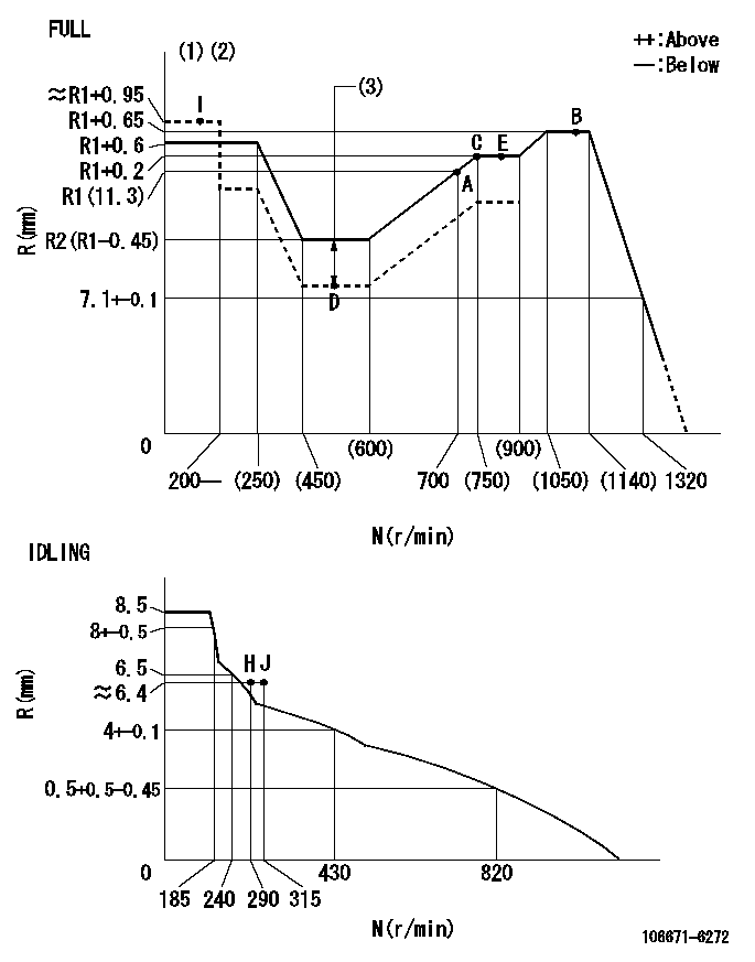
N:Pump speed
R:Rack position (mm)
(1)Torque cam stamping: T1
(2)Tolerance for racks not indicated: +-0.05mm.
(3)Boost compensator stroke: BCL
----------
T1=AE45 BCL=1.75+-0.1mm
----------
----------
T1=AE45 BCL=1.75+-0.1mm
----------
Speed control lever angle
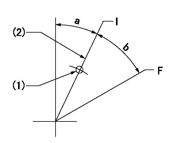
F:Full speed
I:Idle
(1)Use the pin at R = aa
(2)Stopper bolt set position 'H'
----------
aa=35mm
----------
a=27deg+-5deg b=32.5deg+-3deg
----------
aa=35mm
----------
a=27deg+-5deg b=32.5deg+-3deg
Stop lever angle
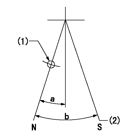
N:Pump normal
S:Stop the pump.
(1)Use the pin at R = aa
(2)Set the stopper bolt so that speed = bb, rack position = cc (confirm non-injection)
----------
aa=40mm bb=0r/min cc=1.5+-0.3mm
----------
a=22deg+-5deg b=41deg+-5deg
----------
aa=40mm bb=0r/min cc=1.5+-0.3mm
----------
a=22deg+-5deg b=41deg+-5deg
0000001501 ACS
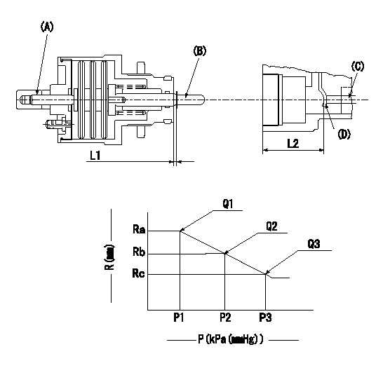
(A) Set screw
(B) Push rod 1
(C) Push rod 2
(D) Lever
1. Aneroid compensator unit adjustment
(1)Screw in (A) to obtain L1.
(2)Select C so that dimension L2 can be obtained.
2. Adjustment when mounting the governor.
(1)Set the speed of the pump to N1 r/min and fix the control lever at the full set position.
(2)Set to full boost.
(3)Screw in the aneroid compensator body to obtain the performance shown in the graph above.
(4)As there is hysterisis, measure when the absolute pressure drops.
(5)Hysterisis must not exceed rack position = h1.
----------
N1=800r/min L1=1.5+-0.5mm L2=37.5+-0.5mm h1=0.15mm
----------
Ra=R3(R1+0.2)mm Rb=(R3-0.4)mm Rc=R3-0.75mm P1=(89.8)+-2.7kPa((674)+-20mmHg) P2=79.4+-2.7kPa(596+-20mmHg) P3=70.1+-0.7kPa(526+-5mmHg) Q1=(149)+-3cm3/1000st Q2=(138.5)cm3/1000st Q3=(129)+-3cm3/1000st
----------
N1=800r/min L1=1.5+-0.5mm L2=37.5+-0.5mm h1=0.15mm
----------
Ra=R3(R1+0.2)mm Rb=(R3-0.4)mm Rc=R3-0.75mm P1=(89.8)+-2.7kPa((674)+-20mmHg) P2=79.4+-2.7kPa(596+-20mmHg) P3=70.1+-0.7kPa(526+-5mmHg) Q1=(149)+-3cm3/1000st Q2=(138.5)cm3/1000st Q3=(129)+-3cm3/1000st
Timing setting

(1)Pump vertical direction
(2)Position of timer's threaded hole at No 1 cylinder's beginning of injection
(3)B.T.D.C.: aa
(4)-
----------
aa=10deg
----------
a=(40deg)
----------
aa=10deg
----------
a=(40deg)
Information:
TECHNICAL INFORMATION BULLETIN June 16, 2004
Truck Engines
C7 (KAL)
C9 (9DG)
C-9 (MTB)
Component Code: 1290SUBJECT: Injector Misfire due to Low/No Fuel Condition
PROBLEM:
Analysis of injectors returned from the field indicates that running the engine out of fuel, excessive air in the fuel, or high fuel inlet restriction may cause an internal injector failure. Multiple injectors failing the Cylinder Cutout Test in Caterpillar Electronic Technician (Cat ET) may indicate this mode of failure. If this occurs, debris from the internal injector failure may collect in the fuel return pressure regulator or fuel return screen (if equipped). See Figure 1.
SOLUTION:
If the Cylinder Cutout Test in Cat ET indicates that multiple injectors have failed, or if the engine has a recent history of injector failures, the fuel return pressure regulator and the fuel return screen need to be inspected for debris. See Figure 1.
Clean the fuel return screen (if equipped). If the engine is equipped with a fuel regulator that has a 90-degree elbow on the cylinder head, then there is a screen inside of the elbow. Remove the 90-degree elbow from the cylinder head and pressure regulator assembly. See Figure 1. Reverse flush any debris out of the elbow screen. If all of the debris cannot be removed from the elbow screen, then replace the 196-6838 90-degree elbow.
Clean/Replace the fuel return pressure regulator assembly as required. If the engine is equipped with a 90-degree elbow screen (see Step 2), the debris should have been caught by the screen. Only replace the 229-8870 pressure regulator if debris is visible on the inlet side of the pressure regulator. Replace failed injectors as indicated by the Cat ET Cylinder Cutout Test.
If the engine did not run out of fuel, make sure that the fuel inlet restriction measured at the fuel transfer pump inlet is within specification (max inlet restriction 4.1 in Hg or 14 kPa). Also, make sure that there is not excessive air in the fuel system by using a sight gauge on the fuel inlet and fuel outlet of the cylinder head. Make sure the fuel tank vent or cap is venting properly.
Note: There have been documented cases of pinched/restricted Original Equipment Manufacturer (OEM) fuel lines and air entry on OEM primary fuel filters.
If the fuel return pressure regulator or the elbow are replaced, return them to the Caterpillar claims room at the address below.
Caterpillar Service Claims Room 8201 N. University Peoria, IL 61615 USA Attn: Geoff Monari / Anant Kasture
Please share this information with your TEPS dealers.
Figure 1
COPYRIGHT 2004 CATERPILLAR
ALL RIGHTS RESERVED