Information injection-pump assembly
BOSCH
F 019 Z10 004
f019z10004
ZEXEL
106671-6262
1066716262
ISUZU
1156032143
1156032143
Rating:
Service parts 106671-6262 INJECTION-PUMP ASSEMBLY:
1.
_
7.
COUPLING PLATE
8.
_
9.
_
11.
Nozzle and Holder
12.
Open Pre:MPa(Kqf/cm2)
17.7{180}/22.1{225}
 BASCOLIN Original Nozzles DLLA152SM070 105025-0700 9 432 611 546")
15.
NOZZLE SET
Include in #1:
106671-6262
as INJECTION-PUMP ASSEMBLY
Cross reference number
BOSCH
F 019 Z10 004
f019z10004
ZEXEL
106671-6262
1066716262
ISUZU
1156032143
1156032143
Zexel num
Bosch num
Firm num
Name
Calibration Data:
Adjustment conditions
Test oil
1404 Test oil ISO4113 or {SAEJ967d}
1404 Test oil ISO4113 or {SAEJ967d}
Test oil temperature
degC
40
40
45
Nozzle and nozzle holder
105780-8140
Bosch type code
EF8511/9A
Nozzle
105780-0000
Bosch type code
DN12SD12T
Nozzle holder
105780-2080
Bosch type code
EF8511/9
Opening pressure
MPa
17.2
Opening pressure
kgf/cm2
175
Injection pipe
Outer diameter - inner diameter - length (mm) mm 8-3-600
Outer diameter - inner diameter - length (mm) mm 8-3-600
Overflow valve
131424-8620
Overflow valve opening pressure
kPa
206
172
240
Overflow valve opening pressure
kgf/cm2
2.1
1.75
2.45
Tester oil delivery pressure
kPa
157
157
157
Tester oil delivery pressure
kgf/cm2
1.6
1.6
1.6
Direction of rotation (viewed from drive side)
Left L
Left L
Injection timing adjustment
Direction of rotation (viewed from drive side)
Left L
Left L
Injection order
1-5-3-6-
2-4
Pre-stroke
mm
4.5
4.47
4.53
Beginning of injection position
Governor side NO.1
Governor side NO.1
Difference between angles 1
Cal 1-5 deg. 60 59.75 60.25
Cal 1-5 deg. 60 59.75 60.25
Difference between angles 2
Cal 1-3 deg. 120 119.75 120.25
Cal 1-3 deg. 120 119.75 120.25
Difference between angles 3
Cal 1-6 deg. 180 179.75 180.25
Cal 1-6 deg. 180 179.75 180.25
Difference between angles 4
Cyl.1-2 deg. 240 239.75 240.25
Cyl.1-2 deg. 240 239.75 240.25
Difference between angles 5
Cal 1-4 deg. 300 299.75 300.25
Cal 1-4 deg. 300 299.75 300.25
Injection quantity adjustment
Adjusting point
-
Rack position
11.3
Pump speed
r/min
700
700
700
Average injection quantity
mm3/st.
149
147
151
Max. variation between cylinders
%
0
-3
3
Basic
*
Fixing the rack
*
Standard for adjustment of the maximum variation between cylinders
*
Injection quantity adjustment_02
Adjusting point
H
Rack position
6.4+-0.5
Pump speed
r/min
290
290
290
Average injection quantity
mm3/st.
10
6.8
13.2
Max. variation between cylinders
%
0
-13
13
Fixing the rack
*
Standard for adjustment of the maximum variation between cylinders
*
Injection quantity adjustment_03
Adjusting point
A
Rack position
R1(11.3)
Pump speed
r/min
700
700
700
Average injection quantity
mm3/st.
149
147
151
Basic
*
Fixing the lever
*
Boost pressure
kPa
60
60
Boost pressure
mmHg
450
450
Injection quantity adjustment_04
Adjusting point
B
Rack position
R1+0.65
Pump speed
r/min
1100
1100
1100
Average injection quantity
mm3/st.
161
155
167
Fixing the lever
*
Boost pressure
kPa
60
60
Boost pressure
mmHg
450
450
Boost compensator adjustment
Pump speed
r/min
500
500
500
Rack position
R2-1.75
Boost pressure
kPa
4
4
6.7
Boost pressure
mmHg
30
30
50
Boost compensator adjustment_02
Pump speed
r/min
500
500
500
Rack position
R2(R1-0.
45)
Boost pressure
kPa
46.7
46.7
46.7
Boost pressure
mmHg
350
350
350
Timer adjustment
Pump speed
r/min
850--
Advance angle
deg.
0
0
0
Remarks
Start
Start
Timer adjustment_02
Pump speed
r/min
800
Advance angle
deg.
0.5
Timer adjustment_03
Pump speed
r/min
875
Advance angle
deg.
1.5
1
2
Remarks
Finish
Finish
Test data Ex:
Governor adjustment
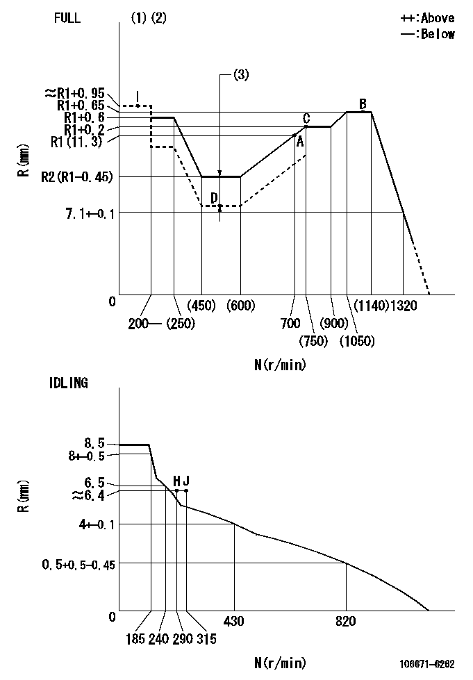
N:Pump speed
R:Rack position (mm)
(1)Torque cam stamping: T1
(2)Tolerance for racks not indicated: +-0.05mm.
(3)Boost compensator stroke: BCL
----------
T1=AE45 BCL=1.75+-0.1mm
----------
----------
T1=AE45 BCL=1.75+-0.1mm
----------
Speed control lever angle
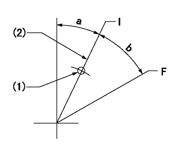
F:Full speed
I:Idle
(1)Use the pin at R = aa
(2)Stopper bolt set position 'H'
----------
aa=35mm
----------
a=27deg+-5deg b=32.5deg+-3deg
----------
aa=35mm
----------
a=27deg+-5deg b=32.5deg+-3deg
Stop lever angle
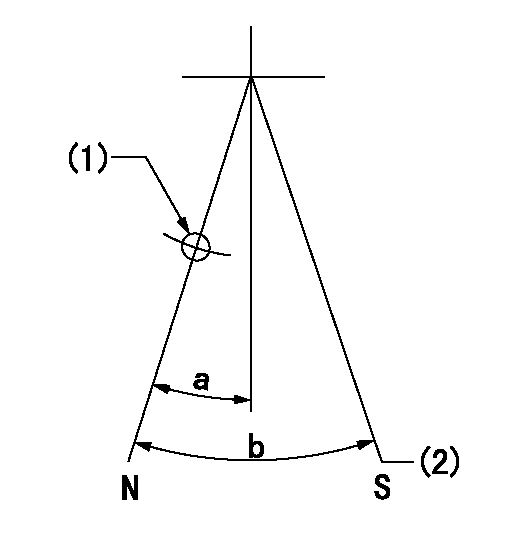
N:Pump normal
S:Stop the pump.
(1)Use the pin at R = aa
(2)Set the stopper bolt so that speed = bb and rack position = cc. (Confirm non-injection.)
----------
aa=40mm bb=0r/min cc=1.5+-0.3mm
----------
a=22deg+-5deg b=41deg+-5deg
----------
aa=40mm bb=0r/min cc=1.5+-0.3mm
----------
a=22deg+-5deg b=41deg+-5deg
Timing setting

(1)Pump vertical direction
(2)Position of timer's threaded hole at the No. 1 cylinder's beginning of injection
(3)B.T.D.C.: aa
(4)-
----------
aa=10deg
----------
a=(40deg)
----------
aa=10deg
----------
a=(40deg)
Information:
This is a 4.0-hour job
PARTS DISPOSITION
Handle the parts in accordance with your Warranty Bulletin on warranty parts handling.
Rework Procedure
Step 1: Ensure CEM has cooled prior to beginning work. Use a temp gun to ensure that the temperature of the injector is at a safe to handle temperature.
Image1.1.1
Step 2: Once the CEM is at a safe temperature to begin work, remove air and DEF line connections at the injector. Ensure all permits and appropriate scaffolding or man-lift type equipment with sufficient personnel are on site or available if needed. This procedure may require two individuals with all the required PPE to handle the weight and distance to reach for work to be performed.
Image1.2.1
Step 3: Remove eight bolts and remove injector assembly from the CEM. This step may require two individuals due to the weight of the injector.
Step 4: Remove the nozzle group from the injector.
Image1.4.1
Step 5: Apply Loctite (nickel free) dry film anti-seize on the threads of the 352-0865 nozzle group. Ensure that only the threads receive anti-seize as the nozzle could suffer plugging if anti-seize contaminates the tip. Install the nozzle group with a new gasket onto the injector group and tighten to 30 +/- 2 Nm.
Image1.5.1
Step 6: Reinstall the injector with new nozzle and new gasket into the CEM matching alignment notches and tighten the eight (8) mounting bolts to standard torque. This step may require two individuals due to the weight of the injector.
Image1.6.1
Step 7: Using a stamping die set, the old injector part number must be removed. This can be accomplished using the X stamp and stamping out all of the part numbers (XXXXXXXX) or a grinder can be used to permanently remove the part number.
Step 8: Using the stamping die set, stamp part number 549-2925 on the flange of the injector as shown in Image 1.6.1.
Step 9: Perform ECM replacement and save all parameters in Product Status Report. Install software part number 590-2884 or latest available on SIS Web into the dosing cabinet ECM.
Step 10: Once flash is complete, perform a complete power cycle of the package and power up: Engine, Control Panel and Dosing system simultaneously. Verify flash and settings are correct in Aftertreatment configuration.
Please note that re-commissioning of the SCR system is not required after the software update if the system has already been commissioned.
Step 11: If Air Assist pressure is low or high then Air Manifold Regulator Adjust Procedure may be required:
Tools Required to Adjust Regulator in Dosing Cabinet:
? Laptop with CatET
? CA3
? 4mm Allen Key
? 8mm Socket to remove access panels
? 0-150 psi gauge with 9/16-18 JIC tees to measure pressure at dosing cabinet inlet
Air Regulator Adjustment Procedure
? Connect CatET to cabinet
? Record air pressure supply before air manifold with a gauge
? Adjust air supply to dosing cabinet if not in spec
? Air Supply in spec. continue
? In ET Override screen, Monitor Air Assist Pressure
? In ET Override screen, Override Air Assist and DEF Return valves
? Monitor and Record Air Assist pressure: Target is 65psi with both valves Override to