Information injection-pump assembly
BOSCH
9 400 610 881
9400610881
ZEXEL
106671-6240
1066716240
ISUZU
1156031580
1156031580

Rating:
Service parts 106671-6240 INJECTION-PUMP ASSEMBLY:
1.
_
7.
COUPLING PLATE
8.
_
9.
_
11.
Nozzle and Holder
1-15300-320-0
12.
Open Pre:MPa(Kqf/cm2)
18.1{185}/22.1{225}
14.
NOZZLE
Include in #1:
106671-6240
as INJECTION-PUMP ASSEMBLY
Cross reference number
BOSCH
9 400 610 881
9400610881
ZEXEL
106671-6240
1066716240
ISUZU
1156031580
1156031580
Zexel num
Bosch num
Firm num
Name
106671-6240
9 400 610 881
1156031580 ISUZU
INJECTION-PUMP ASSEMBLY
6SD1-MTC K 14CA INJECTION PUMP ASSY PE6P,6PD PE
6SD1-MTC K 14CA INJECTION PUMP ASSY PE6P,6PD PE
Calibration Data:
Adjustment conditions
Test oil
1404 Test oil ISO4113 or {SAEJ967d}
1404 Test oil ISO4113 or {SAEJ967d}
Test oil temperature
degC
40
40
45
Nozzle and nozzle holder
105780-8140
Bosch type code
EF8511/9A
Nozzle
105780-0000
Bosch type code
DN12SD12T
Nozzle holder
105780-2080
Bosch type code
EF8511/9
Opening pressure
MPa
17.2
Opening pressure
kgf/cm2
175
Injection pipe
Outer diameter - inner diameter - length (mm) mm 8-3-600
Outer diameter - inner diameter - length (mm) mm 8-3-600
Overflow valve
134424-3920
Overflow valve opening pressure
kPa
127
107
147
Overflow valve opening pressure
kgf/cm2
1.3
1.1
1.5
Tester oil delivery pressure
kPa
157
157
157
Tester oil delivery pressure
kgf/cm2
1.6
1.6
1.6
Direction of rotation (viewed from drive side)
Left L
Left L
Injection timing adjustment
Direction of rotation (viewed from drive side)
Left L
Left L
Injection order
1-5-3-6-
2-4
Pre-stroke
mm
4.2
4.17
4.23
Beginning of injection position
Governor side NO.1
Governor side NO.1
Difference between angles 1
Cal 1-5 deg. 60 59.75 60.25
Cal 1-5 deg. 60 59.75 60.25
Difference between angles 2
Cal 1-3 deg. 120 119.75 120.25
Cal 1-3 deg. 120 119.75 120.25
Difference between angles 3
Cal 1-6 deg. 180 179.75 180.25
Cal 1-6 deg. 180 179.75 180.25
Difference between angles 4
Cyl.1-2 deg. 240 239.75 240.25
Cyl.1-2 deg. 240 239.75 240.25
Difference between angles 5
Cal 1-4 deg. 300 299.75 300.25
Cal 1-4 deg. 300 299.75 300.25
Injection quantity adjustment
Adjusting point
A
Rack position
12
Pump speed
r/min
1150
1150
1150
Average injection quantity
mm3/st.
220
218
222
Max. variation between cylinders
%
0
-2.5
2.5
Basic
*
Fixing the lever
*
Boost pressure
kPa
106.6
106.6
Boost pressure
mmHg
800
800
Injection quantity adjustment_02
Adjusting point
B
Rack position
6+-0.5
Pump speed
r/min
275
275
275
Average injection quantity
mm3/st.
14
12
16
Max. variation between cylinders
%
0
-14
14
Fixing the rack
*
Boost pressure
kPa
0
0
0
Boost pressure
mmHg
0
0
0
Boost compensator adjustment
Pump speed
r/min
650
650
650
Rack position
10.4
Boost pressure
kPa
45.3
42.6
48
Boost pressure
mmHg
340
320
360
Boost compensator adjustment_02
Pump speed
r/min
650
650
650
Rack position
12
Boost pressure
kPa
93.3
93.3
93.3
Boost pressure
mmHg
700
700
700
Timer adjustment
Pump speed
r/min
1150++
Advance angle
deg.
0
0
0
Remarks
Do not advance until starting N = 1150.
Do not advance until starting N = 1150.
Timer adjustment_02
Pump speed
r/min
-
Advance angle
deg.
0.5
0.5
0.5
Remarks
Measure the actual speed, stop
Measure the actual speed, stop
Test data Ex:
Governor adjustment
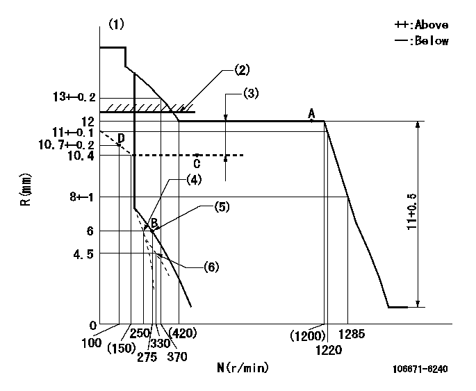
N:Pump speed
R:Rack position (mm)
(1)Tolerance for racks not indicated: +-0.05mm.
(2)Boost compensator excessive fuel lever setting: L1 (at boost pressure 0)
(3)Boost compensator stroke: BCL
(4)Set idle sub-spring
(5)Main spring setting
(6)Damper spring setting
----------
L1=12.2+0.2mm BCL=1.6+-0.1mm
----------
----------
L1=12.2+0.2mm BCL=1.6+-0.1mm
----------
Speed control lever angle
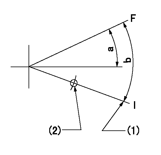
F:Full speed
I:Idle
(1)Stopper bolt setting
(2)Pull at right angles to the hole at R = aa
----------
aa=135mm
----------
a=9.5deg+-5deg b=16deg+-5deg
----------
aa=135mm
----------
a=9.5deg+-5deg b=16deg+-5deg
0000000901
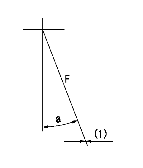
F:Full load
(1)Fix using the stopper bolt.
----------
----------
a=(25deg)+-5deg
----------
----------
a=(25deg)+-5deg
Stop lever angle

N:Pump normal
S:Stop the pump.
(1)Drive side
----------
----------
a=32deg+-5deg b=64deg+-5deg
----------
----------
a=32deg+-5deg b=64deg+-5deg
0000001101
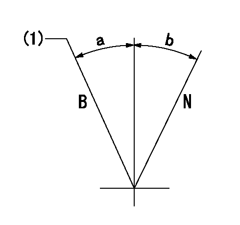
N:Normal
B:When boosted
(1)Rack position = aa at boost pressure 0.
----------
aa=12.2+0.2mm
----------
a=(15deg) b=(15deg)
----------
aa=12.2+0.2mm
----------
a=(15deg) b=(15deg)
Timing setting

(1)Pump vertical direction
(2)Position of timer's threaded hole at No 1 cylinder's beginning of injection
(3)B.T.D.C.: aa
(4)-
----------
aa=14deg
----------
a=(40deg)
----------
aa=14deg
----------
a=(40deg)
Information:
Illustration 74 g02026337 Appendix D
Cleaned Filter Specification
Note: Scope: The following steps determine a properly cleaned Caterpillar filter.Note: This specification applies to filters that were cleaned of ash only. This specification is only valid subsequent to the "Recommended Cleaning Procedure". This specification should not be used to determine if soot filled filters are properly cleaned. All filters must be baked appropriately using the "Recommended Cleaning Procedure" prior to application of this specification.HEALTH AND SAFETY
Wear goggles, gloves, protective clothing, and a National Institute for Occupational Safety and Health (NIOSH) approved P95 or N95 half-face respirator when handling a used Diesel Particulate Filter or Catalytic Converter Muffler. Failure to do so could result in personal injury.
Adhere to all local Health and Safety rules and regulations. Use all the personal protective equipment listed below:
Respirator
Safety shoes
Safety glasses
Latex gloves
Lab coatRESOURCESNecessary equipment:
38 cm (15 inch) long by 0.9 mm (0.04 inch) thick stainless steel probe for "200 cpsi" (Cells/Square inch) filters
Tape measureMETHODEvaluation of a cleaned filter:Note: A filter MUST meet all criteria in this section below to be considered clean.
Inspect both inlet and outlet surfaces for oil/fuel contamination, gouges and/or cracks. No cracks may be visible. Gouges may not be exceed 4.0 mm (0.15 inch) deep.
There must be no filter movement within the filters banding. This movement is defined as the substrate moving past the bent-over flange. The filter must be even or below the bent-over flange.
There must not be any signs of the steel fiber ring coming loose or any mat material (cottony gauze) slipping past the filter. See Illustration 75 below.
The flanges are not damaged beyond repair.
There are no dents deeper than 6.4 mm (0.25 inch) in the outer can of the filter and the outer can is not cracked, torn or otherwise breached.
No more than 20 cells are allowed to be damaged (showing soot) on the outlet face of the filter. Refer to Illustrations 76 and 77.
Inspect the ash depth in the cells using the "Check Cell Depth" instructions below.
Illustration 75 g02026392
Proper placement of the filter within the banding
(1) Outside Can
(2) Bent-over flange
(3) Steel fiber ring
(4) Mat material
(5) FilterNote: Filter must be below the bent over-flange (2).
Illustration 76 g02026398
Acceptable filter with less than 20 damaged cells
Illustration 77 g02026399
Unacceptable filter with too many damaged cells
Check Cell Depth
Check cell depth by dropping the stainless steel probe into a cell location noted by a dot in Illustration 78 below.
Lightly tap the probe with a finger until the probe does not travel into the cell any further. Mark the probe to record the depth.
Illustration 78 g02026405
Measure the distance from the tip of the probe which entered the cell to the mark made on the probe. This distance is the cell depth. Repeat this step 17 times per Illustration 78.
If the probe travels a minimum of 28.6 cm (11.25 inch) in all cells, the filter is considered clean.
If the probe encounters heavy resistance in
Have questions with 106671-6240?
Group cross 106671-6240 ZEXEL
Isuzu
106671-6240
9 400 610 881
1156031580
INJECTION-PUMP ASSEMBLY
6SD1-MTC
6SD1-MTC