Information injection-pump assembly
ZEXEL
106671-6110
1066716110
ISUZU
1156030772
1156030772

Rating:
Cross reference number
ZEXEL
106671-6110
1066716110
ISUZU
1156030772
1156030772
Zexel num
Bosch num
Firm num
Name
Calibration Data:
Adjustment conditions
Test oil
1404 Test oil ISO4113 or {SAEJ967d}
1404 Test oil ISO4113 or {SAEJ967d}
Test oil temperature
degC
40
40
45
Nozzle and nozzle holder
105780-8140
Bosch type code
EF8511/9A
Nozzle
105780-0000
Bosch type code
DN12SD12T
Nozzle holder
105780-2080
Bosch type code
EF8511/9
Opening pressure
MPa
17.2
Opening pressure
kgf/cm2
175
Injection pipe
Outer diameter - inner diameter - length (mm) mm 8-3-600
Outer diameter - inner diameter - length (mm) mm 8-3-600
Overflow valve
134424-1920
Overflow valve opening pressure
kPa
127
107
147
Overflow valve opening pressure
kgf/cm2
1.3
1.1
1.5
Tester oil delivery pressure
kPa
157
157
157
Tester oil delivery pressure
kgf/cm2
1.6
1.6
1.6
Direction of rotation (viewed from drive side)
Left L
Left L
Injection timing adjustment
Direction of rotation (viewed from drive side)
Left L
Left L
Injection order
1-5-3-6-
2-4
Pre-stroke
mm
4.5
4.47
4.53
Beginning of injection position
Governor side NO.1
Governor side NO.1
Difference between angles 1
Cal 1-5 deg. 60 59.75 60.25
Cal 1-5 deg. 60 59.75 60.25
Difference between angles 2
Cal 1-3 deg. 120 119.75 120.25
Cal 1-3 deg. 120 119.75 120.25
Difference between angles 3
Cal 1-6 deg. 180 179.75 180.25
Cal 1-6 deg. 180 179.75 180.25
Difference between angles 4
Cyl.1-2 deg. 240 239.75 240.25
Cyl.1-2 deg. 240 239.75 240.25
Difference between angles 5
Cal 1-4 deg. 300 299.75 300.25
Cal 1-4 deg. 300 299.75 300.25
Injection quantity adjustment
Adjusting point
-
Rack position
11.5
Pump speed
r/min
800
800
800
Average injection quantity
mm3/st.
149
147
151
Max. variation between cylinders
%
0
-3
3
Basic
*
Fixing the rack
*
Standard for adjustment of the maximum variation between cylinders
*
Injection quantity adjustment_02
Adjusting point
H
Rack position
6.4+-0.5
Pump speed
r/min
290
290
290
Average injection quantity
mm3/st.
10.5
7.3
13.7
Max. variation between cylinders
%
0
-13
13
Fixing the rack
*
Standard for adjustment of the maximum variation between cylinders
*
Injection quantity adjustment_03
Adjusting point
A
Rack position
R1(11.5)
Pump speed
r/min
800
800
800
Average injection quantity
mm3/st.
149
147
151
Basic
*
Fixing the lever
*
Boost pressure
kPa
28.7
28.7
Boost pressure
mmHg
215
215
Injection quantity adjustment_04
Adjusting point
B
Rack position
R1+0.3
Pump speed
r/min
1100
1100
1100
Average injection quantity
mm3/st.
153.5
147.5
159.5
Fixing the lever
*
Boost pressure
kPa
28.7
28.7
Boost pressure
mmHg
215
215
Boost compensator adjustment
Pump speed
r/min
500
500
500
Rack position
R2-1.15
Boost pressure
kPa
10
8.7
11.3
Boost pressure
mmHg
75
65
85
Boost compensator adjustment_02
Pump speed
r/min
500
500
500
Rack position
R2(R1-1.
3)
Boost pressure
kPa
15.3
15.3
15.3
Boost pressure
mmHg
115
115
115
Timer adjustment
Pump speed
r/min
850--
Advance angle
deg.
0
0
0
Remarks
Start
Start
Timer adjustment_02
Pump speed
r/min
800
Advance angle
deg.
0.5
Timer adjustment_03
Pump speed
r/min
875
Advance angle
deg.
1.5
1
2
Remarks
Finish
Finish
Test data Ex:
Governor adjustment
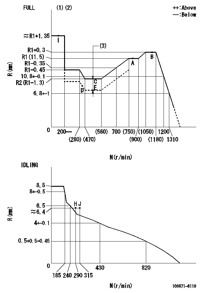
N:Pump speed
R:Rack position (mm)
(1)Torque cam stamping: T1
(2)Tolerance for racks not indicated: +-0.05mm.
(3)Boost compensator stroke: BCL
----------
T1=AD53 BCL=1.15+-0.1mm
----------
----------
T1=AD53 BCL=1.15+-0.1mm
----------
Speed control lever angle
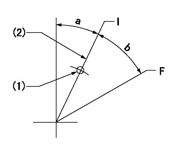
F:Full speed
I:Idle
(1)Use the pin at R = aa
(2)Stopper bolt set position 'H'
----------
aa=35mm
----------
a=27deg+-5deg b=29.5deg+-3deg
----------
aa=35mm
----------
a=27deg+-5deg b=29.5deg+-3deg
Stop lever angle
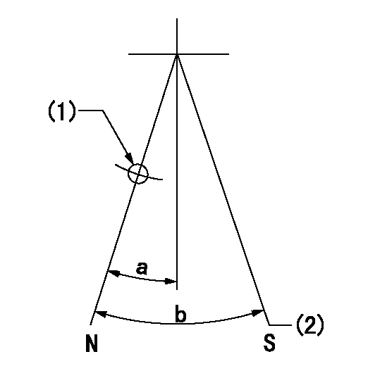
N:Pump normal
S:Stop the pump.
(1)Use the pin at R = aa
(2)Set the stopper bolt so that speed = bb and rack position = cc. (Confirm non-injection.)
----------
aa=40mm bb=0r/min cc=1.5+-0.3mm
----------
a=22deg+-5deg b=41deg+-5deg
----------
aa=40mm bb=0r/min cc=1.5+-0.3mm
----------
a=22deg+-5deg b=41deg+-5deg
0000001501 ACS
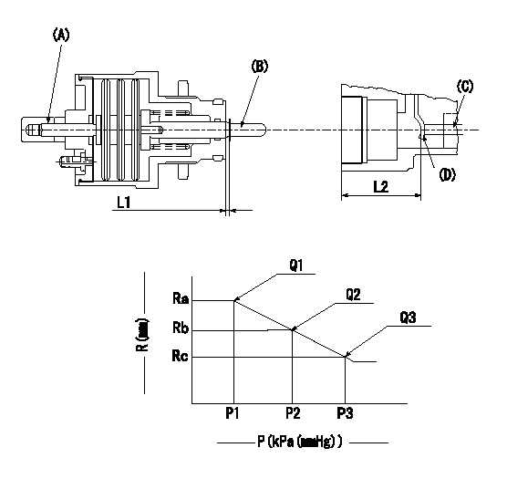
(A) Set screw
(B) Push rod 1
(C) Push rod 2
(D) Lever
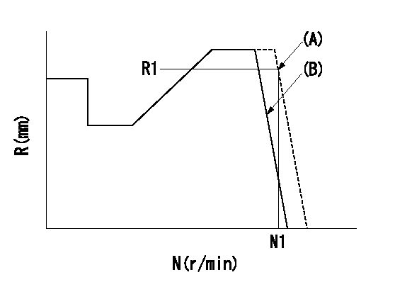
1. Aneroid compensator unit adjustment
(1)Screw in (A) to obtain L1.
(2)Select C so that dimension L2 can be obtained.
2. Adjustment when mounting the governor.
(1)Set the speed of the pump to N1 r/min and fix the control lever at the full set position.
(2)Set to full boost.
(3)Screw in the aneroid compensator body to obtain the performance shown in the graph above.
(4)As there is hysterisis, measure when the absolute pressure drops.
(5)Hysterisis must not exceed rack position = h1.
----------
N1=800r/min L1=1.5+-0.5mm L2=37.5+-0.5mm h1=0.15mm
----------
Ra=R1(11.5)mm Rb=(R1-0.4)mm Rc=R1-0.75mm P1=(89.9)+-2.7kPa((674)+-20mmHg) P2=79.4+-2.7kPa(596+-20mmHg) P3=70.1+-0.7kPa(526+-5mmHg) Q1=149+-2cm3/1000st Q2=(138.5)cm3/1000st Q3=(129)+-2cm3/1000st
----------
N1=800r/min L1=1.5+-0.5mm L2=37.5+-0.5mm h1=0.15mm
----------
Ra=R1(11.5)mm Rb=(R1-0.4)mm Rc=R1-0.75mm P1=(89.9)+-2.7kPa((674)+-20mmHg) P2=79.4+-2.7kPa(596+-20mmHg) P3=70.1+-0.7kPa(526+-5mmHg) Q1=149+-2cm3/1000st Q2=(138.5)cm3/1000st Q3=(129)+-2cm3/1000st
0000001601 TAMPER PROOF
(A): Rotation tamper proof
(B): Full-speed setting
1. Back off the full-speed set bolt.
2. Confirm that the tamper setting position is N1, R1, Q1.
3. At that time, record the angle of the speed lever.
4. After confirming the above setting, set full speed.
----------
N1=1430r/min R1=(6.8)mm Q1=-
----------
----------
N1=1430r/min R1=(6.8)mm Q1=-
----------
Timing setting

(1)Pump vertical direction
(2)Position of timer's threaded hole at No 1 cylinder's beginning of injection
(3)B.T.D.C.: aa
(4)-
----------
aa=10deg
----------
a=(50deg)
----------
aa=10deg
----------
a=(50deg)
Information:
This is a 5.0-hour job
PARTS DISPOSITION
Handle the parts in accordance with your Warranty Bulletin on warranty parts handling.
Rework Procedure
Make sure you have read and understood all of this document before beginning work.
Isolate the generator set before commencing any work on the unit, open generator set breaker, activate Emergency Stop, disconnect the battery cables and either disconnect or open the control circuit breaker for the AC power supply to the battery charger. Ensure all health and safety requirements are adhered to at all times. Also, ensure proper Lock Out-Tag Out procedures are followed at all times while work is being performed on or around the machine. Lock out generator operation and disconnect/lockout all power sources before commencing any work.
1 - Remove the SCR (selective catalyst reduction) side heat shields in order to gain access to the SCR cover. Remove all of the bolts, plates & SCR cover panel. Clean the old gasket material from the Clean Emission Module (CEM) & SCR cover panels.
Reference Image 1.2.1
Image1.2.1
2 - With a new gasket (351-9235) install the SCR cover panel (351-6791), backing plates (351-6794 & 351-6795), washers (7X7729) and original M10 bolts (8T4182) onto the CEM in the following locations:
(7) top center holes
(7) bottom center holes
(1) LH middle hole
(1) RH middle hole
Hand tighten these bolts.
On each corner install a 1" thick plate (512-8186) with (2) washers (7X7729) and (2) longer M10 bolts (8T5005).
Hand tighten these bolts.
Install a nut (5P7970 onto