Information injection-pump assembly
BOSCH
9 400 610 870
9400610870
ZEXEL
106671-6032
1066716032
ISUZU
1156030504
1156030504
Rating:
Service parts 106671-6032 INJECTION-PUMP ASSEMBLY:
1.
_
7.
COUPLING PLATE
8.
_
9.
_
11.
Nozzle and Holder
1-15300-332-0
12.
Open Pre:MPa(Kqf/cm2)
17.7{180}/22.1{225}
15.
NOZZLE SET
Include in #1:
106671-6032
as INJECTION-PUMP ASSEMBLY
Cross reference number
BOSCH
9 400 610 870
9400610870
ZEXEL
106671-6032
1066716032
ISUZU
1156030504
1156030504
Zexel num
Bosch num
Firm num
Name
9 400 610 870
1156030504 ISUZU
INJECTION-PUMP ASSEMBLY
6SD1-TCE * K 14CA PE6P,6PD PE
6SD1-TCE * K 14CA PE6P,6PD PE
Calibration Data:
Adjustment conditions
Test oil
1404 Test oil ISO4113 or {SAEJ967d}
1404 Test oil ISO4113 or {SAEJ967d}
Test oil temperature
degC
40
40
45
Nozzle and nozzle holder
105780-8140
Bosch type code
EF8511/9A
Nozzle
105780-0000
Bosch type code
DN12SD12T
Nozzle holder
105780-2080
Bosch type code
EF8511/9
Opening pressure
MPa
17.2
Opening pressure
kgf/cm2
175
Injection pipe
Outer diameter - inner diameter - length (mm) mm 8-3-600
Outer diameter - inner diameter - length (mm) mm 8-3-600
Overflow valve
134424-1920
Overflow valve opening pressure
kPa
127
107
147
Overflow valve opening pressure
kgf/cm2
1.3
1.1
1.5
Tester oil delivery pressure
kPa
157
157
157
Tester oil delivery pressure
kgf/cm2
1.6
1.6
1.6
Direction of rotation (viewed from drive side)
Left L
Left L
Injection timing adjustment
Direction of rotation (viewed from drive side)
Left L
Left L
Injection order
1-5-3-6-
2-4
Pre-stroke
mm
4.5
4.47
4.53
Beginning of injection position
Governor side NO.1
Governor side NO.1
Difference between angles 1
Cal 1-5 deg. 60 59.75 60.25
Cal 1-5 deg. 60 59.75 60.25
Difference between angles 2
Cal 1-3 deg. 120 119.75 120.25
Cal 1-3 deg. 120 119.75 120.25
Difference between angles 3
Cal 1-6 deg. 180 179.75 180.25
Cal 1-6 deg. 180 179.75 180.25
Difference between angles 4
Cyl.1-2 deg. 240 239.75 240.25
Cyl.1-2 deg. 240 239.75 240.25
Difference between angles 5
Cal 1-4 deg. 300 299.75 300.25
Cal 1-4 deg. 300 299.75 300.25
Injection quantity adjustment
Adjusting point
-
Rack position
11.5
Pump speed
r/min
800
800
800
Average injection quantity
mm3/st.
149
147
151
Max. variation between cylinders
%
0
-3
3
Basic
*
Fixing the rack
*
Standard for adjustment of the maximum variation between cylinders
*
Injection quantity adjustment_02
Adjusting point
H
Rack position
6.4+-0.5
Pump speed
r/min
290
290
290
Average injection quantity
mm3/st.
10.5
7.3
13.7
Max. variation between cylinders
%
0
-13
13
Fixing the rack
*
Standard for adjustment of the maximum variation between cylinders
*
Injection quantity adjustment_03
Adjusting point
A
Rack position
R1(11.5)
Pump speed
r/min
800
800
800
Average injection quantity
mm3/st.
149
147
151
Basic
*
Fixing the lever
*
Boost pressure
kPa
28.7
28.7
Boost pressure
mmHg
215
215
Injection quantity adjustment_04
Adjusting point
B
Rack position
R1+0.3
Pump speed
r/min
1100
1100
1100
Average injection quantity
mm3/st.
153.5
147.5
159.5
Fixing the lever
*
Boost pressure
kPa
28.7
28.7
Boost pressure
mmHg
215
215
Boost compensator adjustment
Pump speed
r/min
500
500
500
Rack position
R2-1.15
Boost pressure
kPa
10
8.7
11.3
Boost pressure
mmHg
75
65
85
Boost compensator adjustment_02
Pump speed
r/min
500
500
500
Rack position
R2(R1-1.
3)
Boost pressure
kPa
15.3
15.3
15.3
Boost pressure
mmHg
115
115
115
Timer adjustment
Pump speed
r/min
850--
Advance angle
deg.
0
0
0
Remarks
Start
Start
Timer adjustment_02
Pump speed
r/min
800
Advance angle
deg.
0.5
Timer adjustment_03
Pump speed
r/min
875
Advance angle
deg.
1.5
1
2
Remarks
Finish
Finish
Test data Ex:
Governor adjustment
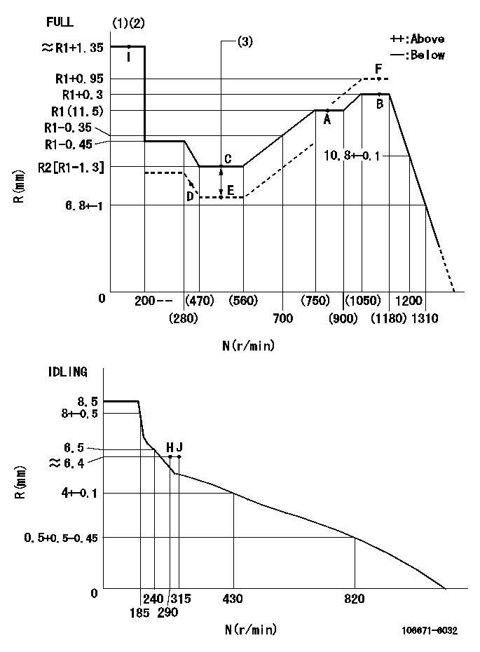
N:Pump speed
R:Rack position (mm)
(1)Torque cam stamping: T1
(2)Tolerance for racks not indicated: +-0.05mm.
(3)Boost compensator stroke: BCL
----------
T1=AD53 BCL=1.15+-0.1mm
----------
----------
T1=AD53 BCL=1.15+-0.1mm
----------
Speed control lever angle
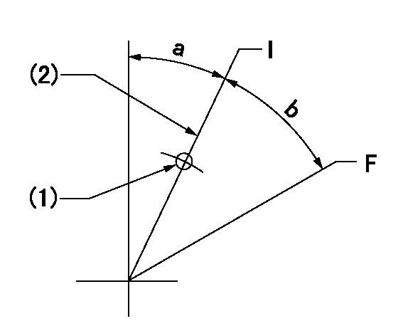
F:Full speed
I:Idle
(1)Use the pin at R = aa
(2)Stopper bolt set position 'H'
----------
aa=35mm
----------
a=27deg+-5deg b=29.5deg+-3deg
----------
aa=35mm
----------
a=27deg+-5deg b=29.5deg+-3deg
Stop lever angle
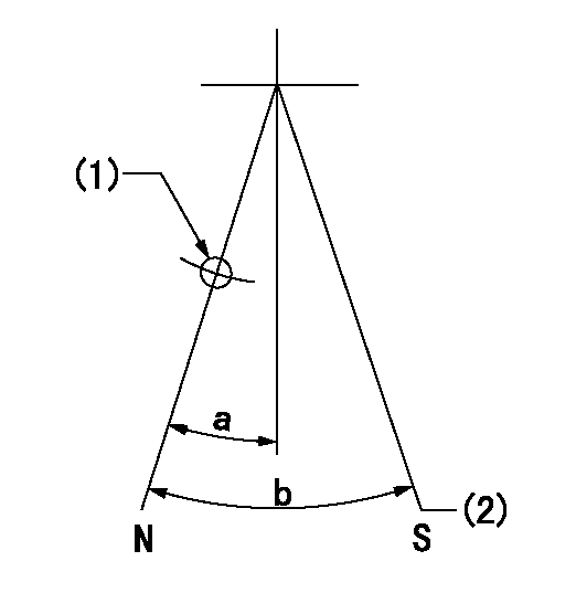
N:Pump normal
S:Stop the pump.
(1)Use the pin at R = aa
(2)Set the stopper bolt so that speed = bb and rack position = cc. (Confirm non-injection.)
----------
aa=40mm bb=0r/min cc=1.5+-0.3mm
----------
a=22deg+-5deg b=41deg+-5deg
----------
aa=40mm bb=0r/min cc=1.5+-0.3mm
----------
a=22deg+-5deg b=41deg+-5deg
0000001501 TAMPER PROOF
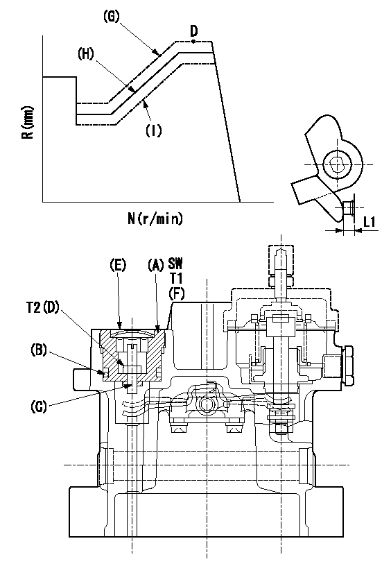
SW:Inner hexagonal SW14
(F): Apply thread lock adhesive .
(G): Full tamper proof
(H): Full boost (Full rack)
(I): 0 boost
1. Mount (C) and (D) after adjusting the boost compensator.
2. Back off the load lever set screw L1 from the end face of the governor housing..
3. Apply boost pressure and set the full load at tamper set position point aa to obtain N1, Q1 and Ra using the screw C.
4. Fix using the nut (D).
5. Next, after adjusting the stop lever, confirm the point aa.
6. Reset the load lever to the full boost rack.
7. After completion of setting, seal using the plug (E).
----------
L1=6+1mm N1=1100r/min Ra=R1+0.95mm Q1=(172.5)mm3/1000st aa=F
----------
T1 T=53.9~73.5N-m(5.5~7.5Kgf-m) T2 T=2.94~4.41N-m(0.3~0.45Kgf-m)
----------
L1=6+1mm N1=1100r/min Ra=R1+0.95mm Q1=(172.5)mm3/1000st aa=F
----------
T1 T=53.9~73.5N-m(5.5~7.5Kgf-m) T2 T=2.94~4.41N-m(0.3~0.45Kgf-m)
0000001601 TAMPER PROOF
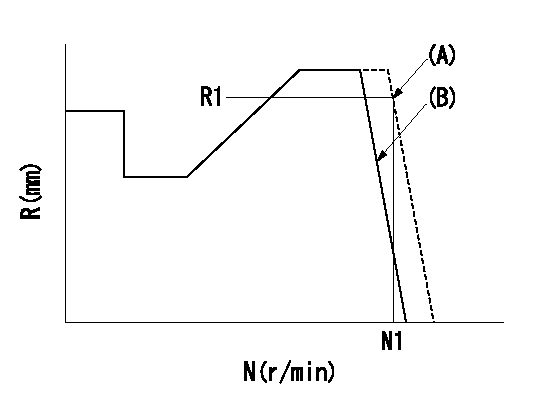
(A): Rotation tamper proof
(B): Full-speed setting
1. Back off the full-speed set bolt.
2. Confirm that the tamper setting position is N1, R1, Q1.
3. At that time, record the angle of the speed lever.
4. After confirming the above setting, set full speed.
----------
N1=1430r/min R1=(6.8)mm Q1=-
----------
----------
N1=1430r/min R1=(6.8)mm Q1=-
----------
Timing setting

(1)Pump vertical direction
(2)Position of timer's threaded hole at No 1 cylinder's beginning of injection
(3)B.T.D.C.: aa
(4)-
----------
aa=10deg
----------
a=(50deg)
----------
aa=10deg
----------
a=(50deg)
Information:
Installation Of 5N7710 Fuel Injection Lines Group
(1) Remove the fuel injection lines from each fuel injection pump to the fuel nozzles. Remove the through-the-head adapter for each set of fuel lines. (2) Put an 8M4437 Seal on each 5N7730 Adapter (1). Install a new 5N7730 Adapter (1) in each bore where the former adapters were removed. Use a 9L9814 Nut (2) on each stud to fasten the adapters in position on cylinder head (3).(3) Install all of the 5N7717 Fuel Lines (4). Use a 5P9795 Seal between each line (4) nut and adapter (1), then use a 5P2060 Seal (5) at the other end of each line (4) nut and the nozzle. (4) Use a 5P9267 Seal between each nut (6) and its injection pump, and use a 5P9795 Seal between each nut (7) and adapter (1), and install the new fuel lines. Fuel lines are as follows: 5N7711 (8), 5N7712 (9), 5N7713 (10), 5N7714 (11), 5N7715 (12) and 5N7716 (13). Tighten all fuel line nuts to 40 7 N m (30 5 lb.ft.).(5) Use 8F1179 Clip (14) with the bolt and washer from the former fuel line clamp, to fasten fuel line (13) to the cylinder head.(6) Use the parts that follow to make a fuel line damper (shock cushion) for fuel lines (9) and (10) [section (A-A)]: 5N7732 Damper (15), 7B1597 Clip (16), 1D4538 Bolt (17), 5N4213 Spacer (18), 4N1278 Strip (19), 9S2299 Strip (20) and 1B5354 Nut (21) with a 9M1974 Washer. Use an S1617 Bolt (22) with a 9M1974 Washer to fasten strip (19) to the cylinder head.(7) At locations (A) and (B), use the parts that follow, to make a fuel line damper for fuel lines (8), (11) and (12); 4N1278 Strip, 9M1974 Washer, 9S2299 Strip, 1A9579 Bolt with 1B5354 Nut and two 5N7732 Dampers. Use an S1617 Bolt with a 9M1974 Washer to fasten 4N1278 Strip to the cylinder hood.Installation of 5N7741 Fuel Lines Drain Group And Alarm Switch
(1) Install a 5K9243 Elbow (1) in each 5N7730 Adapter (2). Connect five 5N7736 Tubes (3) and one 5N7737 Tube (4), then connect five 9L8557 Tees (5) and four 5N7740 Tubes (6) as shown. (2) Use two 5K6437 Clips (7) with S1617 Bolts and 9M1974 Washers, and three 8B6127 Clips (8) with existing bolts, to fasten this assembly into position. (3) Use two S1594 Bolts with 5M2894 Washers and 1D4717 Nuts to fasten 5N7733 Plate (9) to bracket (10) that is already on the engine.(4) Install 4M5317 Bushing (11), 5K9243 Elbow (12), 8B1931 Bushing (13) and 9L8496 Tee (14) with 9L8492 Plug (15) in 2N9768 Liquid Level Switch (16). Install 5N7739 Tube (17) in elbow (12), then use two S1616 Bolts, four 5P537 Washers, two 1B4330 Nuts and a 2B2404 Clip (18) to fasten switch (16), with tube (17), to plate (9) as shown. Vent passage in tube (17) must be open to the atmosphere at all times for the correct operation of this system.(5) Connect 5N7738 Tube (19) as shown, then
