Information injection-pump assembly
BOSCH
9 400 616 888
9400616888
ZEXEL
106671-5910
1066715910
NISSAN-DIESEL
1679096610
1679096610
Rating:
Service parts 106671-5910 INJECTION-PUMP ASSEMBLY:
1.
_
7.
COUPLING PLATE
8.
_
9.
_
11.
Nozzle and Holder
16600-96609
12.
Open Pre:MPa(Kqf/cm2)
17.7{180}/22.6{230}
15.
NOZZLE SET
Include in #1:
106671-5910
as INJECTION-PUMP ASSEMBLY
Cross reference number
BOSCH
9 400 616 888
9400616888
ZEXEL
106671-5910
1066715910
NISSAN-DIESEL
1679096610
1679096610
Zexel num
Bosch num
Firm num
Name
106671-5910
9 400 616 888
1679096610 NISSAN-DIESEL
INJECTION-PUMP ASSEMBLY
PF6TA K 14CA INJECTION PUMP ASSY PE6P,6PD PE
PF6TA K 14CA INJECTION PUMP ASSY PE6P,6PD PE
Calibration Data:
Adjustment conditions
Test oil
1404 Test oil ISO4113 or {SAEJ967d}
1404 Test oil ISO4113 or {SAEJ967d}
Test oil temperature
degC
40
40
45
Nozzle and nozzle holder
105780-8140
Bosch type code
EF8511/9A
Nozzle
105780-0000
Bosch type code
DN12SD12T
Nozzle holder
105780-2080
Bosch type code
EF8511/9
Opening pressure
MPa
17.2
Opening pressure
kgf/cm2
175
Injection pipe
Outer diameter - inner diameter - length (mm) mm 8-3-600
Outer diameter - inner diameter - length (mm) mm 8-3-600
Overflow valve
134424-0020
Overflow valve opening pressure
kPa
157
123
191
Overflow valve opening pressure
kgf/cm2
1.6
1.25
1.95
Tester oil delivery pressure
kPa
157
157
157
Tester oil delivery pressure
kgf/cm2
1.6
1.6
1.6
Direction of rotation (viewed from drive side)
Right R
Right R
Injection timing adjustment
Direction of rotation (viewed from drive side)
Right R
Right R
Injection order
1-4-2-6-
3-5
Pre-stroke
mm
3.9
3.85
3.95
Beginning of injection position
Drive side NO.1
Drive side NO.1
Difference between angles 1
Cal 1-4 deg. 60 59.5 60.5
Cal 1-4 deg. 60 59.5 60.5
Difference between angles 2
Cyl.1-2 deg. 120 119.5 120.5
Cyl.1-2 deg. 120 119.5 120.5
Difference between angles 3
Cal 1-6 deg. 180 179.5 180.5
Cal 1-6 deg. 180 179.5 180.5
Difference between angles 4
Cal 1-3 deg. 240 239.5 240.5
Cal 1-3 deg. 240 239.5 240.5
Difference between angles 5
Cal 1-5 deg. 300 299.5 300.5
Cal 1-5 deg. 300 299.5 300.5
Injection quantity adjustment
Adjusting point
A
Rack position
11.3
Pump speed
r/min
700
700
700
Average injection quantity
mm3/st.
179.5
177.5
181.5
Max. variation between cylinders
%
0
-4
4
Basic
*
Fixing the lever
*
Boost pressure
kPa
89.3
89.3
Boost pressure
mmHg
670
670
Injection quantity adjustment_02
Adjusting point
D
Rack position
6+-0.5
Pump speed
r/min
300
300
300
Average injection quantity
mm3/st.
11.5
10.5
12.5
Max. variation between cylinders
%
0
-10
10
Fixing the rack
*
Boost pressure
kPa
0
0
0
Boost pressure
mmHg
0
0
0
Boost compensator adjustment
Pump speed
r/min
500
500
500
Rack position
9.3
Boost pressure
kPa
6.7
1.4
12
Boost pressure
mmHg
50
10
90
Boost compensator adjustment_02
Pump speed
r/min
500
500
500
Rack position
(11.3)
Boost pressure
kPa
77.3
74.6
80
Boost pressure
mmHg
580
560
600
Timer adjustment
Pump speed
r/min
750--
Advance angle
deg.
0
0
0
Remarks
Start
Start
Timer adjustment_02
Pump speed
r/min
700
Advance angle
deg.
0.5
Timer adjustment_03
Pump speed
r/min
1050
Advance angle
deg.
2
1.5
2.5
Remarks
Finish
Finish
Test data Ex:
Governor adjustment
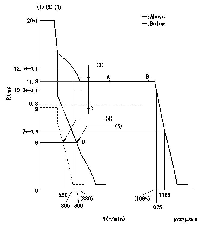
N:Pump speed
R:Rack position (mm)
(1)Target notch: K
(2)Tolerance for racks not indicated: +-0.05mm.
(3)Boost compensator stroke: BCL
(4)Set idle sub-spring
(5)Main spring setting
(6)Perform governor adjustment at an ambient temperature of at least 15 deg C (boost compensator start spring is shape memory alloy).
----------
K=9 BCL=(2)mm
----------
----------
K=9 BCL=(2)mm
----------
Speed control lever angle

F:Full speed
I:Idle
(1)Stopper bolt setting
----------
----------
a=4deg+-5deg b=22deg+-5deg
----------
----------
a=4deg+-5deg b=22deg+-5deg
Stop lever angle

N:Pump normal
S:Stop the pump.
----------
----------
a=26deg+-5deg b=53deg+-5deg
----------
----------
a=26deg+-5deg b=53deg+-5deg
Timing setting

(1)Pump vertical direction
(2)Coupling's key groove position at No 1 cylinder's beginning of injection
(3)-
(4)-
----------
----------
a=(25deg)
----------
----------
a=(25deg)
Information:
Outside Leaks
Possible Causes/Corrections Leaks In Hoses Or ConnectionsCheck all hoses and connections for visual signs of leakage. If no leaks are seen, look for damage to hoses or loose clamps. Leaks In The Radiator And/Or Expansion TankPut pressure to the radiator and/or expansion tank with the 9S8140 Cooling System Pressurizing Pump Group and check for leaks. Leaks In The HeaterPut pressure to the cooling system with the 9S8140 Cooling System Pressurizing Pump Group and check the heater for leaks. Leaks In The Water PumpCheck the water pump for leaks before starting the engine, then start the engine and look for leaks. If there are leaks at the water pump, repair or install a new water pump. Cylinder Head Gasket LeakageLook for leaks along the surface of the cylinder head gasket. If you see leaks, install a new head gasket.Refer to Special Instruction, SEHS9565, 3306 Cylinder Head To Block Joint Repair Procedure for additional information on Combustion Gas Leakage Tests.Coolant Leaks At The Overflow Tube
Possible Causes/Corrections Defective Pressure Cap Or Relief ValveCheck the sealing surfaces of the pressure cap and the radiator to be sure the cap is sealing correctly. Check the opening pressure and sealing ability of the pressure cap or relief valve with the 9S8140 Cooling System Pressurizing Pump Group. Engine Runs Too HotIf coolant temperature is too high, pressure will be high enough to move the cap off of the sealing surface in the radiator and cause coolant loss through the overflow tube. See "Overheating" in Cooling System Troubleshooting Section. Expansion Tank Too Small Or Installed WrongThe expansion tank can be either a part of the radiator or it can be installed separately from the radiator. The expansion tank must be large enough to hold the expansion of the coolant as it gets warm or has sudden changes in pressure. Make sure the expansion tank is installed correctly, and the size is according to the recommendations of the truck manufacturer. Cylinder Head Gasket Leakage Or Crack(s) In Cylinder Head Or Cylinder BlockRemove the radiator cap and, with the engine running, look for air bubbles in the coolant. Bubbles in the coolant are a sign of probable leakage at the head gasket. Remove the cylinder head from the engine. Check cylinder head, cylinder walls and head gasket surface of the cylinder block for cracks. When the head is installed, use a new head gasket, spacer plate gasket, water seals, and O-ring seals.Inside Leakage
Possible Causes/Corrections Cylinder Head Gasket LeakageIf the cylinder head gasket leaks between a water passage and an opening into the crankcase, coolant will get into the crankcase.Refer to Special Instruction, SEHS9565, 3306 Cylinder Head To Block Joint Repair Procedure for additional information on Combustion Gas Leakage Tests. Crack(s) In Cylinder HeadCrack(s) in the upper surface of the cylinder head, or an area between a water passage and an opening into the crankcase, can allow coolant to get into the crankcase. Crack(s) In Cylinder BlockCrack(s) in the cylinder block between a water passage and the crankcase
Have questions with 106671-5910?
Group cross 106671-5910 ZEXEL
Nissan-Diesel
106671-5910
9 400 616 888
1679096610
INJECTION-PUMP ASSEMBLY
PF6TA
PF6TA